Data Structures | |
| struct | _acmp_config |
| Configuration for ACMP. More... | |
| struct | _acmp_channel_config |
| Configuration for channel. More... | |
| struct | _acmp_filter_config |
| Configuration for filter. More... | |
| struct | _acmp_dac_config |
| Configuration for DAC. More... | |
| struct | _acmp_round_robin_config |
| Configuration for round robin mode. More... | |
| struct | _acmp_discrete_mode_config |
| Configuration for discrete mode. More... | |
Initialization and deinitialization | |
| void | ACMP_Init (CMP_Type *base, const acmp_config_t *config) |
| Initializes the ACMP. | |
| void | ACMP_Deinit (CMP_Type *base) |
| Deinitializes the ACMP. | |
| void | ACMP_GetDefaultConfig (acmp_config_t *config) |
| Gets the default configuration for ACMP. | |
Basic Operations | |
| void | ACMP_Enable (CMP_Type *base, bool enable) |
| Enables or disables the ACMP. | |
| void | ACMP_EnableLinkToDAC (CMP_Type *base, bool enable) |
| Enables the link from CMP to DAC enable. | |
| void | ACMP_SetChannelConfig (CMP_Type *base, const acmp_channel_config_t *config) |
| Sets the channel configuration. | |
Advanced Operations | |
| void | ACMP_EnableDMA (CMP_Type *base, bool enable) |
| Enables or disables DMA. | |
| void | ACMP_EnableWindowMode (CMP_Type *base, bool enable) |
| Enables or disables window mode. | |
| void | ACMP_SetFilterConfig (CMP_Type *base, const acmp_filter_config_t *config) |
| Configures the filter. | |
| void | ACMP_SetDACConfig (CMP_Type *base, const acmp_dac_config_t *config) |
| Configures the internal DAC. | |
| void | ACMP_SetRoundRobinConfig (CMP_Type *base, const acmp_round_robin_config_t *config) |
| Configures the round robin mode. | |
| void | ACMP_SetRoundRobinPreState (CMP_Type *base, uint32_t mask) |
| Defines the pre-set state of channels in round robin mode. | |
| static uint32_t | ACMP_GetRoundRobinStatusFlags (CMP_Type *base) |
| Gets the channel input changed flags in round robin mode. | |
| void | ACMP_ClearRoundRobinStatusFlags (CMP_Type *base, uint32_t mask) |
| Clears the channel input changed flags in round robin mode. | |
| static uint32_t | ACMP_GetRoundRobinResult (CMP_Type *base) |
| Gets the round robin result. | |
Interrupts | |
| void | ACMP_EnableInterrupts (CMP_Type *base, uint32_t mask) |
| Enables interrupts. | |
| void | ACMP_DisableInterrupts (CMP_Type *base, uint32_t mask) |
| Disables interrupts. | |
Status | |
| uint32_t | ACMP_GetStatusFlags (CMP_Type *base) |
| Gets status flags. | |
| void | ACMP_ClearStatusFlags (CMP_Type *base, uint32_t mask) |
| Clears status flags. | |
Discrete mode | |
| void | ACMP_SetDiscreteModeConfig (CMP_Type *base, const acmp_discrete_mode_config_t *config) |
| Configure the discrete mode. | |
| void | ACMP_GetDefaultDiscreteModeConfig (acmp_discrete_mode_config_t *config) |
| Get the default configuration for discrete mode setting. | |
Detailed Description
Typedef Documentation
◆ acmp_channel_config_t
| typedef struct _acmp_channel_config acmp_channel_config_t |
Configuration for channel.
The comparator's port can be input from channel mux or DAC. If port input is from channel mux, detailed channel number for the mux should be configured.
◆ acmp_config_t
| typedef struct _acmp_config acmp_config_t |
Configuration for ACMP.
◆ acmp_dac_config_t
| typedef struct _acmp_dac_config acmp_dac_config_t |
Configuration for DAC.
◆ acmp_dac_work_mode_t
| typedef enum _acmp_dac_work_mode acmp_dac_work_mode_t |
Internal DAC's work mode.
◆ acmp_discrete_clock_source_t
| typedef enum _acmp_discrete_clock_source acmp_discrete_clock_source_t |
Discrete mode clock selection.
◆ acmp_discrete_mode_config_t
| typedef struct _acmp_discrete_mode_config acmp_discrete_mode_config_t |
Configuration for discrete mode.
◆ acmp_discrete_phase_time_t
| typedef enum _acmp_discrete_phase_time acmp_discrete_phase_time_t |
ACMP discrete phase time selection. There are two phases for sampling input signals, phase 1 and phase 2.
◆ acmp_discrete_sample_time_t
| typedef enum _acmp_discrete_sample_time acmp_discrete_sample_time_t |
ACMP discrete sample selection. These values configures the analog comparator sampling timing (speicified by the discrete mode clock period T which is selected by acmp_discrete_clock_source_t) in discrete mode.
◆ acmp_filter_config_t
| typedef struct _acmp_filter_config acmp_filter_config_t |
Configuration for filter.
◆ acmp_fixed_port_t
| typedef enum _acmp_fixed_port acmp_fixed_port_t |
Fixed mux port.
◆ acmp_hysteresis_mode_t
| typedef enum _acmp_hysteresis_mode acmp_hysteresis_mode_t |
Comparator hard block hysteresis control.
See chip data sheet to get the actual hysteresis value with each level.
◆ acmp_offset_mode_t
| typedef enum _acmp_offset_mode acmp_offset_mode_t |
Comparator hard block offset control.
If OFFSET level is 1, then there is no hysteresis in the case of positive port input crossing negative port input in the positive direction (or negative port input crossing positive port input in the negative direction). Hysteresis still exists for positive port input crossing negative port input in the falling direction. If OFFSET level is 0, then the hysteresis selected by acmp_hysteresis_mode_t is valid for both directions.
◆ acmp_port_input_t
| typedef enum _acmp_port_input acmp_port_input_t |
Port input source.
◆ acmp_reference_voltage_source_t
CMP Voltage Reference source.
◆ acmp_round_robin_config_t
| typedef struct _acmp_round_robin_config acmp_round_robin_config_t |
Configuration for round robin mode.
Enumeration Type Documentation
◆ _acmp_dac_work_mode
| enum _acmp_dac_work_mode |
Internal DAC's work mode.
| Enumerator | |
|---|---|
| kACMP_DACWorkLowSpeedMode | DAC is selected to work in low speed and low power mode. |
| kACMP_DACWorkHighSpeedMode | DAC is selected to work in high speed high power mode. |
Definition at line 104 of file fsl_acmp.h.
◆ _acmp_discrete_clock_source
Discrete mode clock selection.
| Enumerator | |
|---|---|
| kACMP_DiscreteClockSlow | Slow clock (32kHz) is used as the discrete mode clock. |
| kACMP_DiscreteClockFast | Fast clock (16-20MHz) is used as the discrete mode clock. |
Definition at line 179 of file fsl_acmp.h.
◆ _acmp_discrete_phase_time
ACMP discrete phase time selection. There are two phases for sampling input signals, phase 1 and phase 2.
Definition at line 206 of file fsl_acmp.h.
◆ _acmp_discrete_sample_time
ACMP discrete sample selection. These values configures the analog comparator sampling timing (speicified by the discrete mode clock period T which is selected by acmp_discrete_clock_source_t) in discrete mode.
Definition at line 190 of file fsl_acmp.h.
◆ _acmp_fixed_port
| enum _acmp_fixed_port |
Fixed mux port.
| Enumerator | |
|---|---|
| kACMP_FixedPlusPort | Only the inputs to the Minus port are swept in each round. |
| kACMP_FixedMinusPort | Only the inputs to the Plus port are swept in each round. |
Definition at line 96 of file fsl_acmp.h.
◆ _acmp_hysteresis_mode
Comparator hard block hysteresis control.
See chip data sheet to get the actual hysteresis value with each level.
| Enumerator | |
|---|---|
| kACMP_HysteresisLevel0 | Offset is level 0 and Hysteresis is level 0. |
| kACMP_HysteresisLevel1 | Offset is level 0 and Hysteresis is level 1. |
| kACMP_HysteresisLevel2 | Offset is level 0 and Hysteresis is level 2. |
| kACMP_HysteresisLevel3 | Offset is level 0 and Hysteresis is level 3. |
Definition at line 71 of file fsl_acmp.h.
◆ _acmp_interrupt_enable
Interrupt enable/disable mask.
Definition at line 35 of file fsl_acmp.h.
◆ _acmp_offset_mode
| enum _acmp_offset_mode |
Comparator hard block offset control.
If OFFSET level is 1, then there is no hysteresis in the case of positive port input crossing negative port input in the positive direction (or negative port input crossing positive port input in the negative direction). Hysteresis still exists for positive port input crossing negative port input in the falling direction. If OFFSET level is 0, then the hysteresis selected by acmp_hysteresis_mode_t is valid for both directions.
| Enumerator | |
|---|---|
| kACMP_OffsetLevel0 | The comparator hard block output has level 0 offset internally. |
| kACMP_OffsetLevel1 | The comparator hard block output has level 1 offset internally. |
Definition at line 59 of file fsl_acmp.h.
◆ _acmp_port_input
| enum _acmp_port_input |
Port input source.
| Enumerator | |
|---|---|
| kACMP_PortInputFromDAC | Port input from the 8-bit DAC output. |
| kACMP_PortInputFromMux | Port input from the analog 8-1 mux. |
Definition at line 88 of file fsl_acmp.h.
◆ _acmp_reference_voltage_source
CMP Voltage Reference source.
| Enumerator | |
|---|---|
| kACMP_VrefSourceVin1 | Vin1 is selected as resistor ladder network supply reference Vin. |
| kACMP_VrefSourceVin2 | Vin2 is selected as resistor ladder network supply reference Vin. |
Definition at line 80 of file fsl_acmp.h.
◆ _acmp_status_flags
| enum _acmp_status_flags |
Status flag mask.
Definition at line 43 of file fsl_acmp.h.
Function Documentation
◆ ACMP_ClearRoundRobinStatusFlags()
| void ACMP_ClearRoundRobinStatusFlags | ( | CMP_Type * | base, |
| uint32_t | mask | ||
| ) |
Clears the channel input changed flags in round robin mode.
- Parameters
-
base ACMP peripheral base address. mask Mask of channel index. Available range is channel0:0x01 to channel7:0x80.
brief Clears the channel input changed flags in round robin mode.
param base ACMP peripheral base address. param mask Mask of channel index. Available range is channel0:0x01 to channel7:0x80.
Definition at line 470 of file fsl_acmp.c.
◆ ACMP_ClearStatusFlags()
| void ACMP_ClearStatusFlags | ( | CMP_Type * | base, |
| uint32_t | mask | ||
| ) |
Clears status flags.
- Parameters
-
base ACMP peripheral base address. mask Status flags mask. See "_acmp_status_flags".
brief Clears status flags.
param base ACMP peripheral base address. param mask Status flags mask. See "_acmp_status_flags".
Definition at line 589 of file fsl_acmp.c.
Referenced by comp_lld_get_status().

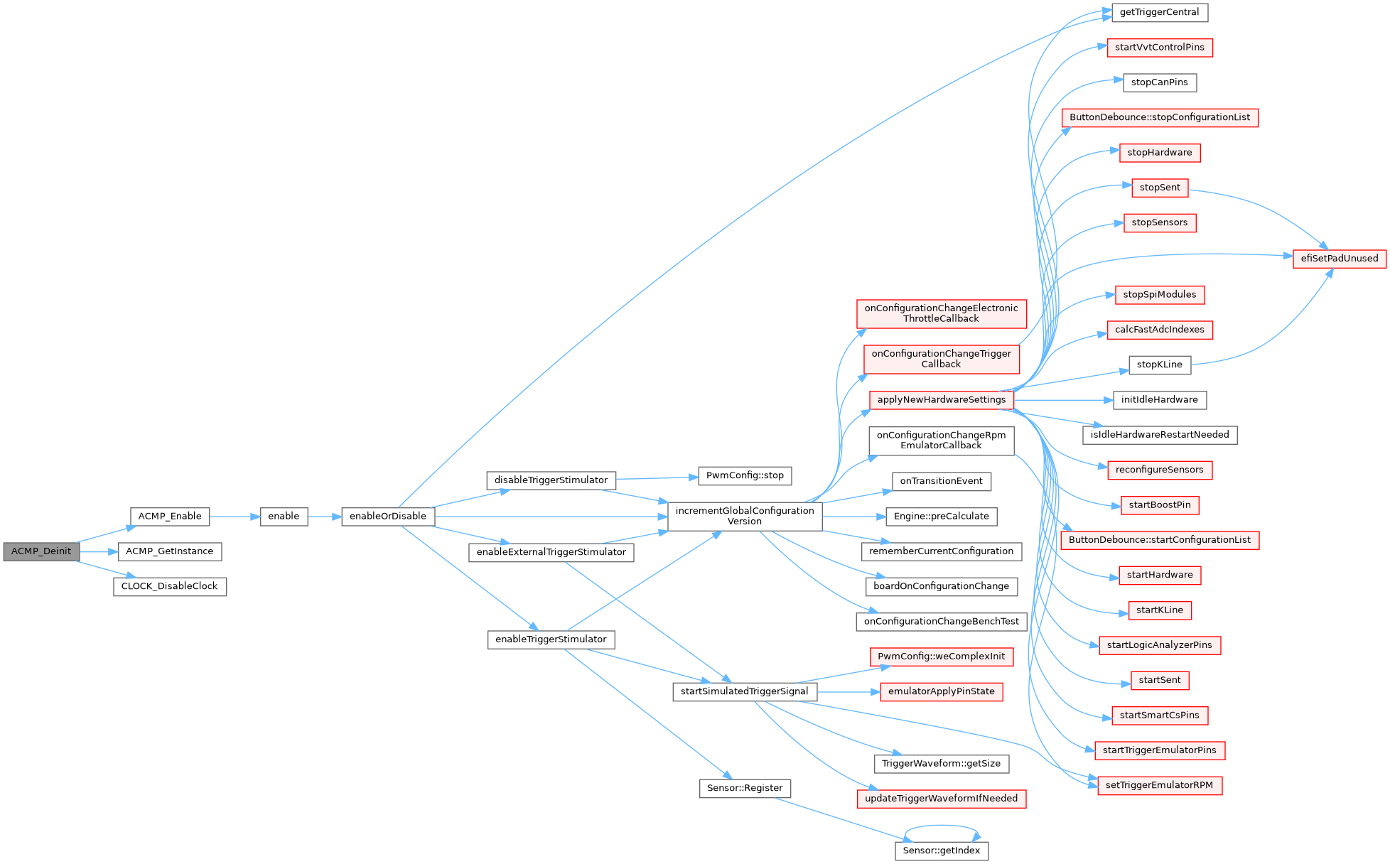
◆ ACMP_Deinit()
| void ACMP_Deinit | ( | CMP_Type * | base | ) |
Deinitializes the ACMP.
- Parameters
-
base ACMP peripheral base address.
brief Deinitializes the ACMP.
param base ACMP peripheral base address.
Definition at line 120 of file fsl_acmp.c.
Referenced by comp_lld_stop().
◆ ACMP_DisableInterrupts()
| void ACMP_DisableInterrupts | ( | CMP_Type * | base, |
| uint32_t | mask | ||
| ) |
Disables interrupts.
- Parameters
-
base ACMP peripheral base address. mask Interrupts mask. See "_acmp_interrupt_enable".
brief Disables interrupts.
param base ACMP peripheral base address. param mask Interrupts mask. See "_acmp_interrupt_enable".
Definition at line 522 of file fsl_acmp.c.
Referenced by comp_lld_disable().

◆ ACMP_Enable()
| void ACMP_Enable | ( | CMP_Type * | base, |
| bool | enable | ||
| ) |
Enables or disables the ACMP.
- Parameters
-
base ACMP peripheral base address. enable True to enable the ACMP.
brief Enables or disables the ACMP.
param base ACMP peripheral base address. param enable True to enable the ACMP.
Definition at line 172 of file fsl_acmp.c.
Referenced by ACMP_Deinit(), ACMP_Init(), comp_lld_disable(), and comp_lld_enable().


◆ ACMP_EnableDMA()
| void ACMP_EnableDMA | ( | CMP_Type * | base, |
| bool | enable | ||
| ) |
Enables or disables DMA.
- Parameters
-
base ACMP peripheral base address. enable True to enable DMA.
brief Enables or disables DMA.
param base ACMP peripheral base address. param enable True to enable DMA.
Definition at line 260 of file fsl_acmp.c.

◆ ACMP_EnableInterrupts()
| void ACMP_EnableInterrupts | ( | CMP_Type * | base, |
| uint32_t | mask | ||
| ) |
Enables interrupts.
- Parameters
-
base ACMP peripheral base address. mask Interrupts mask. See "_acmp_interrupt_enable".
brief Enables interrupts.
param base ACMP peripheral base address. param mask Interrupts mask. See "_acmp_interrupt_enable".
Definition at line 485 of file fsl_acmp.c.
Referenced by comp_lld_enable().

◆ ACMP_EnableLinkToDAC()
| void ACMP_EnableLinkToDAC | ( | CMP_Type * | base, |
| bool | enable | ||
| ) |
Enables the link from CMP to DAC enable.
When this bit is set, the DAC enable/disable is controlled by the bit CMP_C0[EN] instead of CMP_C1[DACEN].
- Parameters
-
base ACMP peripheral base address. enable Enable the feature or not.
brief Enables the link from CMP to DAC enable.
When this bit is set, the DAC enable/disable is controlled by the bit CMP_C0[EN] instead of CMP_C1[DACEN].
param base ACMP peripheral base address. param enable Enable the feature or not.
Definition at line 196 of file fsl_acmp.c.

◆ ACMP_EnableWindowMode()
| void ACMP_EnableWindowMode | ( | CMP_Type * | base, |
| bool | enable | ||
| ) |
Enables or disables window mode.
- Parameters
-
base ACMP peripheral base address. enable True to enable window mode.
brief Enables or disables window mode.
param base ACMP peripheral base address. param enable True to enable window mode.
Definition at line 281 of file fsl_acmp.c.

◆ ACMP_GetDefaultConfig()
| void ACMP_GetDefaultConfig | ( | acmp_config_t * | config | ) |
Gets the default configuration for ACMP.
This function initializes the user configuration structure to default value. The default value are:
Example:
- Parameters
-
config Pointer to ACMP configuration structure.
brief Gets the default configuration for ACMP.
This function initializes the user configuration structure to default value. The default value are:
Example: code config->enableHighSpeed = false; config->enableInvertOutput = false; config->useUnfilteredOutput = false; config->enablePinOut = false; config->enableHysteresisBothDirections = false; config->hysteresisMode = kACMP_hysteresisMode0; endcode
param config Pointer to ACMP configuration structure.
Definition at line 148 of file fsl_acmp.c.
Referenced by comp_lld_start().

◆ ACMP_GetDefaultDiscreteModeConfig()
| void ACMP_GetDefaultDiscreteModeConfig | ( | acmp_discrete_mode_config_t * | config | ) |
Get the default configuration for discrete mode setting.
- Parameters
-
config Pointer to configuration structure to be restored with the setting values.
brief Get the default configuration for discrete mode setting.
param config Pointer to configuration structure to be restored with the setting values.
Definition at line 645 of file fsl_acmp.c.
◆ ACMP_GetRoundRobinResult()
|
inlinestatic |
Gets the round robin result.
Note that the set-pre-state has different circuit with get-round-robin-result in the SOC even though they are same bits. So ACMP_GetRoundRobinResult() can't return the same value as the value are set by ACMP_SetRoundRobinPreState.
- Parameters
-
base ACMP peripheral base address.
- Returns
- Mask of round robin channel result. Available range is channel0:0x01 to channel7:0x80.
Definition at line 451 of file fsl_acmp.h.
◆ ACMP_GetRoundRobinStatusFlags()
|
inlinestatic |
Gets the channel input changed flags in round robin mode.
- Parameters
-
base ACMP peripheral base address.
- Returns
- Mask of channel input changed asserted flags. Available range is channel0:0x01 to channel7:0x80.
Definition at line 429 of file fsl_acmp.h.
◆ ACMP_GetStatusFlags()
| uint32_t ACMP_GetStatusFlags | ( | CMP_Type * | base | ) |
Gets status flags.
- Parameters
-
base ACMP peripheral base address.
- Returns
- Status flags asserted mask. See "_acmp_status_flags".
brief Gets status flags.
param base ACMP peripheral base address. return Status flags asserted mask. See "_acmp_status_flags".
Definition at line 559 of file fsl_acmp.c.
Referenced by comp_lld_get_status().

◆ ACMP_Init()
| void ACMP_Init | ( | CMP_Type * | base, |
| const acmp_config_t * | config | ||
| ) |
Initializes the ACMP.
The default configuration can be got by calling ACMP_GetDefaultConfig().
- Parameters
-
base ACMP peripheral base address. config Pointer to ACMP configuration structure.
brief Initializes the ACMP.
The default configuration can be got by calling ACMP_GetDefaultConfig().
param base ACMP peripheral base address. param config Pointer to ACMP configuration structure.
Definition at line 70 of file fsl_acmp.c.
Referenced by comp_lld_start().


◆ ACMP_SetChannelConfig()
| void ACMP_SetChannelConfig | ( | CMP_Type * | base, |
| const acmp_channel_config_t * | config | ||
| ) |
Sets the channel configuration.
Note that the plus/minus mux's setting is only valid when the positive/negative port's input isn't from DAC but from channel mux.
Example:
- Parameters
-
base ACMP peripheral base address. config Pointer to channel configuration structure.
brief Sets the channel configuration.
Note that the plus/minus mux's setting is only valid when the positive/negative port's input isn't from DAC but from channel mux.
Example: code acmp_channel_config_t configStruct = {0}; configStruct.positivePortInput = kACMP_PortInputFromDAC; configStruct.negativePortInput = kACMP_PortInputFromMux; configStruct.minusMuxInput = 1U; ACMP_SetChannelConfig(CMP0, &configStruct); endcode
param base ACMP peripheral base address. param config Pointer to channel configuration structure.
Definition at line 230 of file fsl_acmp.c.
Referenced by comp_lld_channel_enable().

◆ ACMP_SetDACConfig()
| void ACMP_SetDACConfig | ( | CMP_Type * | base, |
| const acmp_dac_config_t * | config | ||
| ) |
Configures the internal DAC.
Example:
- Parameters
-
base ACMP peripheral base address. config Pointer to DAC configuration structure. "NULL" is for disabling the feature.
brief Configures the internal DAC.
Example: code acmp_dac_config_t configStruct = {0}; configStruct.referenceVoltageSource = kACMP_VrefSourceVin1; configStruct.DACValue = 20U; configStruct.enableOutput = false; configStruct.workMode = kACMP_DACWorkLowSpeedMode; ACMP_SetDACConfig(CMP0, &configStruct); endcode
param base ACMP peripheral base address. param config Pointer to DAC configuration structure. "NULL" is for disabling the feature.
Definition at line 348 of file fsl_acmp.c.
Referenced by comp_lld_set_dac_value().

◆ ACMP_SetDiscreteModeConfig()
| void ACMP_SetDiscreteModeConfig | ( | CMP_Type * | base, |
| const acmp_discrete_mode_config_t * | config | ||
| ) |
Configure the discrete mode.
Configure the discrete mode when supporting 3V domain with 1.8V core.
- Parameters
-
base ACMP peripheral base address. config Pointer to configuration structure. See "acmp_discrete_mode_config_t".
brief Configure the discrete mode.
Configure the discrete mode when supporting 3V domain with 1.8V core.
param base ACMP peripheral base address. param config Pointer to configuration structure. See "acmp_discrete_mode_config_t".
Definition at line 615 of file fsl_acmp.c.
◆ ACMP_SetFilterConfig()
| void ACMP_SetFilterConfig | ( | CMP_Type * | base, |
| const acmp_filter_config_t * | config | ||
| ) |
Configures the filter.
The filter can be enabled when the filter count is bigger than 1, the filter period is greater than 0 and the sample clock is from divided bus clock or the filter is bigger than 1 and the sample clock is from external clock. Detailed usage can be got from the reference manual.
Example:
- Parameters
-
base ACMP peripheral base address. config Pointer to filter configuration structure.
brief Configures the filter.
The filter can be enabled when the filter count is bigger than 1, the filter period is greater than 0 and the sample clock is from divided bus clock or the filter is bigger than 1 and the sample clock is from external clock. Detailed usage can be got from the reference manual.
Example: code acmp_filter_config_t configStruct = {0}; configStruct.filterCount = 5U; configStruct.filterPeriod = 200U; configStruct.enableSample = false; ACMP_SetFilterConfig(CMP0, &configStruct); endcode
param base ACMP peripheral base address. param config Pointer to filter configuration structure.
Definition at line 315 of file fsl_acmp.c.
Referenced by comp_lld_start().

◆ ACMP_SetRoundRobinConfig()
| void ACMP_SetRoundRobinConfig | ( | CMP_Type * | base, |
| const acmp_round_robin_config_t * | config | ||
| ) |
Configures the round robin mode.
Example:
- Parameters
-
base ACMP peripheral base address. config Pointer to round robin mode configuration structure. "NULL" is for disabling the feature.
brief Configures the round robin mode.
Example: code acmp_round_robin_config_t configStruct = {0}; configStruct.fixedPort = kACMP_FixedPlusPort; configStruct.fixedChannelNumber = 3U; configStruct.checkerChannelMask = 0xF7U; configStruct.sampleClockCount = 0U; configStruct.delayModulus = 0U; ACMP_SetRoundRobinConfig(CMP0, &configStruct); endcode param base ACMP peripheral base address. param config Pointer to round robin mode configuration structure. "NULL" is for disabling the feature.
Definition at line 406 of file fsl_acmp.c.
◆ ACMP_SetRoundRobinPreState()
| void ACMP_SetRoundRobinPreState | ( | CMP_Type * | base, |
| uint32_t | mask | ||
| ) |
Defines the pre-set state of channels in round robin mode.
Note: The pre-state has different circuit with get-round-robin-result in the SOC even though they are same bits. So get-round-robin-result can't return the same value as the value are set by pre-state.
- Parameters
-
base ACMP peripheral base address. mask Mask of round robin channel index. Available range is channel0:0x01 to channel7:0x80.
brief Defines the pre-set state of channels in round robin mode.
Note: The pre-state has different circuit with get-round-robin-result in the SOC even though they are same bits. So get-round-robin-result can't return the same value as the value are set by pre-state.
param base ACMP peripheral base address. param mask Mask of round robin channel index. Available range is channel0:0x01 to channel7:0x80.
Definition at line 453 of file fsl_acmp.c.
Variable Documentation
◆ checkerChannelMask
| uint32_t _acmp_round_robin_config::checkerChannelMask |
Mask of checker channel index. Available range is channel0:0x01 to channel7:0x80 for round-robin checker.
Definition at line 170 of file fsl_acmp.h.
◆ clockSource
| acmp_discrete_clock_source_t _acmp_discrete_mode_config::clockSource |
Select the clock source in order to generate the requiried timing for comparator to work in discrete mode.
Definition at line 227 of file fsl_acmp.h.
◆ DACValue
| uint32_t _acmp_dac_config::DACValue |
Value for DAC Output Voltage. Available range is 0-63.
Definition at line 154 of file fsl_acmp.h.
Referenced by comp_lld_set_dac_value().
◆ delayModulus
| uint32_t _acmp_round_robin_config::delayModulus |
Comparator and DAC initialization delay modulus.
Definition at line 173 of file fsl_acmp.h.
◆ enableHighSpeed
| bool _acmp_config::enableHighSpeed |
Enable High Speed (HS) comparison mode.
Definition at line 118 of file fsl_acmp.h.
Referenced by comp_lld_start().
◆ enableInvertOutput
| bool _acmp_config::enableInvertOutput |
Enable inverted comparator output.
Definition at line 119 of file fsl_acmp.h.
Referenced by comp_lld_start().
◆ enableNegativeChannelDiscreteMode
| bool _acmp_discrete_mode_config::enableNegativeChannelDiscreteMode |
Negative Channel Continuous Mode Enable. By default, the continuous mode is used.
Definition at line 223 of file fsl_acmp.h.
◆ enableOutput
| bool _acmp_dac_config::enableOutput |
Enable the DAC output.
Definition at line 157 of file fsl_acmp.h.
◆ enablePinOut
| bool _acmp_config::enablePinOut |
The comparator output is available on the associated pin.
Definition at line 121 of file fsl_acmp.h.
◆ enablePositiveChannelDiscreteMode
| bool _acmp_discrete_mode_config::enablePositiveChannelDiscreteMode |
Positive Channel Continuous Mode Enable. By default, the continuous mode is used.
Definition at line 221 of file fsl_acmp.h.
◆ enableResistorDivider
| bool _acmp_discrete_mode_config::enableResistorDivider |
Resistor Divider Enable is used to enable the resistor divider for the inputs when they come from 3v domain and their values are above 1.8v.
Definition at line 225 of file fsl_acmp.h.
◆ enableSample
| bool _acmp_filter_config::enableSample |
Using external SAMPLE as sampling clock input, or using divided bus clock.
Definition at line 145 of file fsl_acmp.h.
Referenced by comp_lld_start().
◆ filterCount
| uint32_t _acmp_filter_config::filterCount |
Filter Sample Count. Available range is 1-7, 0 would cause the filter disabled.
Definition at line 146 of file fsl_acmp.h.
Referenced by comp_lld_start().
◆ filterPeriod
| uint32_t _acmp_filter_config::filterPeriod |
Filter Sample Period. The divider to bus clock. Available range is 0-255.
Definition at line 147 of file fsl_acmp.h.
Referenced by comp_lld_start().
◆ fixedChannelNumber
| uint32_t _acmp_round_robin_config::fixedChannelNumber |
Indicates which channel is fixed in the fixed mux port.
Definition at line 169 of file fsl_acmp.h.
◆ fixedPort
| acmp_fixed_port_t _acmp_round_robin_config::fixedPort |
Fixed mux port.
Definition at line 168 of file fsl_acmp.h.
◆ hysteresisMode
| acmp_hysteresis_mode_t _acmp_config::hysteresisMode |
◆ minusMuxInput
| uint32_t _acmp_channel_config::minusMuxInput |
Minus mux input channel(0~7).
Definition at line 139 of file fsl_acmp.h.
Referenced by comp_lld_channel_enable().
◆ negativePortInput
| acmp_port_input_t _acmp_channel_config::negativePortInput |
Input source of the comparator's negative port.
Definition at line 137 of file fsl_acmp.h.
Referenced by comp_lld_channel_enable().
◆ offsetMode
| acmp_offset_mode_t _acmp_config::offsetMode |
Offset mode.
Definition at line 115 of file fsl_acmp.h.
◆ phase1Time
| acmp_discrete_phase_time_t _acmp_discrete_mode_config::phase1Time |
Select the ACMP phase 1 sampling time.
Definition at line 230 of file fsl_acmp.h.
◆ phase2Time
| acmp_discrete_phase_time_t _acmp_discrete_mode_config::phase2Time |
Select the ACMP phase 2 sampling time.
Definition at line 231 of file fsl_acmp.h.
◆ plusMuxInput
| uint32_t _acmp_channel_config::plusMuxInput |
Plus mux input channel(0~7).
Definition at line 135 of file fsl_acmp.h.
Referenced by comp_lld_channel_enable().
◆ positivePortInput
| acmp_port_input_t _acmp_channel_config::positivePortInput |
Input source of the comparator's positive port.
Definition at line 133 of file fsl_acmp.h.
Referenced by comp_lld_channel_enable().
◆ referenceVoltageSource
| acmp_reference_voltage_source_t _acmp_dac_config::referenceVoltageSource |
Supply voltage reference source.
Definition at line 153 of file fsl_acmp.h.
Referenced by comp_lld_start().
◆ sampleClockCount
| uint32_t _acmp_round_robin_config::sampleClockCount |
Specifies how many round-robin clock cycles(0~3) later the sample takes place.
Definition at line 172 of file fsl_acmp.h.
◆ sampleTime
| acmp_discrete_sample_time_t _acmp_discrete_mode_config::sampleTime |
Select the ACMP total sampling time period.
Definition at line 229 of file fsl_acmp.h.
◆ useUnfilteredOutput
| bool _acmp_config::useUnfilteredOutput |
Set compare output(COUT) to equal COUTA(true) or COUT(false).
Definition at line 120 of file fsl_acmp.h.
Referenced by comp_lld_start().
◆ workMode
| acmp_dac_work_mode_t _acmp_dac_config::workMode |
Definition at line 161 of file fsl_acmp.h.