Not to be too terribly rude here, but you guys really don't have any idea how effective engine management works.

The whole MAF load thing is a big question. You might know how much air you have with a hotwire sensor but coming up with a load value is more tricky.
-Ford normalizes the value to "standard" conditions and displacement. A "Load" value of 1.0 indicates that the engine is ingesting exactly the same amount of air each rev as would be present in the volume of one cylinder at sea level at 25degC air temps. (I think) This means that virtually no naturally aspirated engine will see a load value equal to or greater than one. This basically involves dividing absolute airflow (in g/s) by RPM, Displacement
-GM, Subaru and many others leave out the displacement factor. You end up with g/cyl as the final measurement
-Nissan and a lot of early Bosch systems use (essentially) injector pulsewidth as a load index. When you think about it, this actually works moderately well especially if you somehow factor out target AF
Many MAP-sensor based systems simply use a RPM vs pressure table. Crude but effective.
There is a trend towards interconnected models in most of the better engine management offerings available. The big idea here is to be able to change one piece of the puzzle and not have to re-tune the the whole system. I *really* think that it would be foolish to not implement something along these lines. It's not that hard to do when you're building something but adding this degree of modularity down the road... This basically requires thinking about engine management as a series of interconnected systems.
What I mean:
-You have a fueling model. This model takes as an input the amount of air present (in grams/s or grams/cyl), a target lambda value, fuel stoichiometry (either specified or measured from flex fuel sensor) and spits out the amount of fuel required in g/s.
-You have a fuel delivery model. This model takes as an input the amount of fuel required in g/s, the number of injectors present (so you can do things like staged injection) and figures out how much fuel to try to deliver with each injector.
-You have an injector model. This model takes the amount of fuel to deliver with an injector (in g/s), injector latency data (presumably measured in lab), injector flow rate data (presumably measured in lab), fuel density (specified / measured) and comes up with an actual injector pulsewidth to fire the injector.
Or on the airflow side:
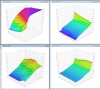
-You have a speed-density model that takes a pressure reading (directly from a MAP sensor or from a MAP sensor and then averaged or ...), a configured value for engine displacement and then an estimated charge temp along with a configured Volumetric Efficiency table which then spits out airflow in g/s (i.e. classic GM, Megasquirt, older Motec, Haltech, BigStuff3, Fast XFI, etc.) Main weakness IMHO: density correction algorithms (i.e. charge temp prediction or figuring out how hot the air is going into the motor. Weather sensitivity)
-You can have different charge air temp algorithms that use a mixture of IAT, ECT, RPM, etc. to alter the way air temps are predicted
-You have a Alpha-N model that takes a throttle input and RPM and spits out an expected airflow value.
-You can combine Alpha-N and speed-density, making the (mostly correct) assumption that the movement of the throttle plate is going to be one of the better predictors of how engine efficiency changes. The setup for this is much like a "traditional" Alpha-N but the main tunable table contains efficiency values which are then used to scale a RPM x pressure volumetric efficiency table.
-You can use a classic hotwire MAF algorithm with a voltage-output style MAF, a MAF transfer function and spit out g/s.
-You can use a classic hotwire MAF algorithm set up to use a frequency-output style MAF like newer GM, Ford, Mitsubishi use and a MAF transfer function and spit out g/s.
-You can take a classic MAF algorithm and attempt to provide more robust correction but taking advantage of the integrated airflow sensor that is almost always present along with King's law equations
-You can do MAF anticipation using the present reading, past readings, rates of change in order to try and anticipate MAF values in situations where the MAF signal changes too rapidly to be entirely accurate.
-You can take an average of the MAF input over a longer period of time in order to smooth out uneven pulses, i.e. large camshaft at low RPM idle.
-You can have a transient airflow model that attempts to predict how much airflow is present during sudden RPM or throttle changes when all of your primary metering systems are going to fail.
...
So what's the big advantage here? Why are more and more OEM and aftermarket systems heading this direction?
One big reason: failures and error handling.
What happens on an OEM vehicle if you walk up to it while it is running and unplug the MAF? Does it shut down? In most cases, the ECU will throw the check-engine-light on to indicate that a fault has occurred and then it SWITCHES TO A DIFFERENT MODEL FOR AIRFLOW. Ok the MAF has failed and we can't figure out how much air we have from that? Substitute Alpha-N from a backup system. Structure your systems in such a way that the Alpha-N metering system and MAF metering system have compatible outputs for airflow and BAM the car continues to run.
GM has done this on nearly every one of their vehicles since the late 90s: vehicles come with both a MAP and MAF sensor. The MAP sensor is primarily used close to idle and lower RPMs. The system switches over to being much more of a pure-MAF system at higher RPMs with more laminar flow. Transient fueling (even at high RPMs) switches back to using Alpha-N and the MAP sensor as inputs.
Ford's factory supercharged vehicles are equipped with supercharger inlet pressure sensors that are used by a transient model during sudden changes in throttle until the MAF can stabilize.
This rant is long enough already...
p.s. I just bought a dyno. Woohoo!


