Data Structures | |
| struct | _lpspi_master_config |
| LPSPI master configuration structure. More... | |
| struct | _lpspi_slave_config |
| LPSPI slave configuration structure. More... | |
| struct | _lpspi_transfer |
| LPSPI master/slave transfer structure. More... | |
| struct | _lpspi_master_handle |
| LPSPI master transfer handle structure used for transactional API. More... | |
| struct | _lpspi_slave_handle |
| LPSPI slave transfer handle structure used for transactional API. More... | |
Driver version | |
| enum | _lpspi_status { kStatus_LPSPI_Busy = MAKE_STATUS(kStatusGroup_LPSPI, 0) , kStatus_LPSPI_Error = MAKE_STATUS(kStatusGroup_LPSPI, 1) , kStatus_LPSPI_Idle = MAKE_STATUS(kStatusGroup_LPSPI, 2) , kStatus_LPSPI_OutOfRange = MAKE_STATUS(kStatusGroup_LPSPI, 3) } |
| Status for the LPSPI driver. More... | |
| enum | _lpspi_flags { kLPSPI_TxDataRequestFlag = LPSPI_SR_TDF_MASK , kLPSPI_RxDataReadyFlag = LPSPI_SR_RDF_MASK , kLPSPI_WordCompleteFlag = LPSPI_SR_WCF_MASK , kLPSPI_FrameCompleteFlag = LPSPI_SR_FCF_MASK , kLPSPI_TransferCompleteFlag = LPSPI_SR_TCF_MASK , kLPSPI_TransmitErrorFlag = LPSPI_SR_TEF_MASK , kLPSPI_ReceiveErrorFlag = LPSPI_SR_REF_MASK , kLPSPI_DataMatchFlag = LPSPI_SR_DMF_MASK , kLPSPI_ModuleBusyFlag = LPSPI_SR_MBF_MASK , kLPSPI_AllStatusFlag } |
| LPSPI status flags in SPIx_SR register. More... | |
| enum | _lpspi_interrupt_enable { kLPSPI_TxInterruptEnable = LPSPI_IER_TDIE_MASK , kLPSPI_RxInterruptEnable = LPSPI_IER_RDIE_MASK , kLPSPI_WordCompleteInterruptEnable = LPSPI_IER_WCIE_MASK , kLPSPI_FrameCompleteInterruptEnable = LPSPI_IER_FCIE_MASK , kLPSPI_TransferCompleteInterruptEnable = LPSPI_IER_TCIE_MASK , kLPSPI_TransmitErrorInterruptEnable = LPSPI_IER_TEIE_MASK , kLPSPI_ReceiveErrorInterruptEnable = LPSPI_IER_REIE_MASK , kLPSPI_DataMatchInterruptEnable = LPSPI_IER_DMIE_MASK , kLPSPI_AllInterruptEnable } |
| LPSPI interrupt source. More... | |
| enum | _lpspi_dma_enable { kLPSPI_TxDmaEnable = LPSPI_DER_TDDE_MASK , kLPSPI_RxDmaEnable = LPSPI_DER_RDDE_MASK } |
| LPSPI DMA source. More... | |
| enum | _lpspi_master_slave_mode { kLPSPI_Master = 1U , kLPSPI_Slave = 0U } |
| LPSPI master or slave mode configuration. More... | |
| enum | _lpspi_which_pcs_config { kLPSPI_Pcs0 = 0U , kLPSPI_Pcs1 = 1U , kLPSPI_Pcs2 = 2U , kLPSPI_Pcs3 = 3U } |
| LPSPI Peripheral Chip Select (PCS) configuration (which PCS to configure). More... | |
| enum | _lpspi_pcs_polarity_config { kLPSPI_PcsActiveHigh = 1U , kLPSPI_PcsActiveLow = 0U } |
| LPSPI Peripheral Chip Select (PCS) Polarity configuration. More... | |
| enum | _lpspi_pcs_polarity { kLPSPI_Pcs0ActiveLow = 1U << 0 , kLPSPI_Pcs1ActiveLow = 1U << 1 , kLPSPI_Pcs2ActiveLow = 1U << 2 , kLPSPI_Pcs3ActiveLow = 1U << 3 , kLPSPI_PcsAllActiveLow = 0xFU } |
| LPSPI Peripheral Chip Select (PCS) Polarity. More... | |
| enum | _lpspi_clock_polarity { kLPSPI_ClockPolarityActiveHigh = 0U , kLPSPI_ClockPolarityActiveLow = 1U } |
| LPSPI clock polarity configuration. More... | |
| enum | _lpspi_clock_phase { kLPSPI_ClockPhaseFirstEdge = 0U , kLPSPI_ClockPhaseSecondEdge = 1U } |
| LPSPI clock phase configuration. More... | |
| enum | _lpspi_shift_direction { kLPSPI_MsbFirst = 0U , kLPSPI_LsbFirst = 1U } |
| LPSPI data shifter direction options. More... | |
| enum | _lpspi_host_request_select { kLPSPI_HostReqExtPin = 0U , kLPSPI_HostReqInternalTrigger = 1U } |
| LPSPI Host Request select configuration. More... | |
| enum | _lpspi_match_config { kLPSI_MatchDisabled = 0x0U , kLPSI_1stWordEqualsM0orM1 = 0x2U , kLPSI_AnyWordEqualsM0orM1 = 0x3U , kLPSI_1stWordEqualsM0and2ndWordEqualsM1 = 0x4U , kLPSI_AnyWordEqualsM0andNxtWordEqualsM1 = 0x5U , kLPSI_1stWordAndM1EqualsM0andM1 = 0x6U , kLPSI_AnyWordAndM1EqualsM0andM1 = 0x7U } |
| LPSPI Match configuration options. More... | |
| enum | _lpspi_pin_config { kLPSPI_SdiInSdoOut = 0U , kLPSPI_SdiInSdiOut = 1U , kLPSPI_SdoInSdoOut = 2U , kLPSPI_SdoInSdiOut = 3U } |
| LPSPI pin (SDO and SDI) configuration. More... | |
| enum | _lpspi_data_out_config { kLpspiDataOutRetained = 0U , kLpspiDataOutTristate = 1U } |
| LPSPI data output configuration. More... | |
| enum | _lpspi_transfer_width { kLPSPI_SingleBitXfer = 0U , kLPSPI_TwoBitXfer = 1U , kLPSPI_FourBitXfer = 2U } |
| LPSPI transfer width configuration. More... | |
| enum | _lpspi_delay_type { kLPSPI_PcsToSck = 1U , kLPSPI_LastSckToPcs , kLPSPI_BetweenTransfer } |
| LPSPI delay type selection. More... | |
| enum | _lpspi_transfer_config_flag_for_master { kLPSPI_MasterPcs0 = 0U << LPSPI_MASTER_PCS_SHIFT , kLPSPI_MasterPcs1 = 1U << LPSPI_MASTER_PCS_SHIFT , kLPSPI_MasterPcs2 = 2U << LPSPI_MASTER_PCS_SHIFT , kLPSPI_MasterPcs3 = 3U << LPSPI_MASTER_PCS_SHIFT , kLPSPI_MasterPcsContinuous = 1U << 20 , kLPSPI_MasterByteSwap } |
| Use this enumeration for LPSPI master transfer configFlags. More... | |
| enum | _lpspi_transfer_config_flag_for_slave { kLPSPI_SlavePcs0 = 0U << LPSPI_SLAVE_PCS_SHIFT , kLPSPI_SlavePcs1 = 1U << LPSPI_SLAVE_PCS_SHIFT , kLPSPI_SlavePcs2 = 2U << LPSPI_SLAVE_PCS_SHIFT , kLPSPI_SlavePcs3 = 3U << LPSPI_SLAVE_PCS_SHIFT , kLPSPI_SlaveByteSwap } |
| Use this enumeration for LPSPI slave transfer configFlags. More... | |
| enum | _lpspi_transfer_state { kLPSPI_Idle = 0x0U , kLPSPI_Busy , kLPSPI_Error } |
| LPSPI transfer state, which is used for LPSPI transactional API state machine. More... | |
| typedef enum _lpspi_master_slave_mode | lpspi_master_slave_mode_t |
| LPSPI master or slave mode configuration. | |
| typedef enum _lpspi_which_pcs_config | lpspi_which_pcs_t |
| LPSPI Peripheral Chip Select (PCS) configuration (which PCS to configure). | |
| typedef enum _lpspi_pcs_polarity_config | lpspi_pcs_polarity_config_t |
| LPSPI Peripheral Chip Select (PCS) Polarity configuration. | |
| typedef enum _lpspi_clock_polarity | lpspi_clock_polarity_t |
| LPSPI clock polarity configuration. | |
| typedef enum _lpspi_clock_phase | lpspi_clock_phase_t |
| LPSPI clock phase configuration. | |
| typedef enum _lpspi_shift_direction | lpspi_shift_direction_t |
| LPSPI data shifter direction options. | |
| typedef enum _lpspi_host_request_select | lpspi_host_request_select_t |
| LPSPI Host Request select configuration. | |
| typedef enum _lpspi_match_config | lpspi_match_config_t |
| LPSPI Match configuration options. | |
| typedef enum _lpspi_pin_config | lpspi_pin_config_t |
| LPSPI pin (SDO and SDI) configuration. | |
| typedef enum _lpspi_data_out_config | lpspi_data_out_config_t |
| LPSPI data output configuration. | |
| typedef enum _lpspi_transfer_width | lpspi_transfer_width_t |
| LPSPI transfer width configuration. | |
| typedef enum _lpspi_delay_type | lpspi_delay_type_t |
| LPSPI delay type selection. | |
| typedef struct _lpspi_master_config | lpspi_master_config_t |
| LPSPI master configuration structure. | |
| typedef struct _lpspi_slave_config | lpspi_slave_config_t |
| LPSPI slave configuration structure. | |
| typedef struct _lpspi_master_handle | lpspi_master_handle_t |
| Forward declaration of the _lpspi_master_handle typedefs. | |
| typedef struct _lpspi_slave_handle | lpspi_slave_handle_t |
| Forward declaration of the _lpspi_slave_handle typedefs. | |
| typedef void(* | lpspi_master_transfer_callback_t) (LPSPI_Type *base, lpspi_master_handle_t *handle, status_t status, void *userData) |
| Master completion callback function pointer type. | |
| typedef void(* | lpspi_slave_transfer_callback_t) (LPSPI_Type *base, lpspi_slave_handle_t *handle, status_t status, void *userData) |
| Slave completion callback function pointer type. | |
| typedef struct _lpspi_transfer | lpspi_transfer_t |
| LPSPI master/slave transfer structure. | |
| volatile uint8_t | g_lpspiDummyData [] |
| Global variable for dummy data value setting. | |
Initialization and deinitialization | |
| void | LPSPI_MasterInit (LPSPI_Type *base, const lpspi_master_config_t *masterConfig, uint32_t srcClock_Hz) |
| Initializes the LPSPI master. | |
| void | LPSPI_MasterGetDefaultConfig (lpspi_master_config_t *masterConfig) |
| Sets the lpspi_master_config_t structure to default values. | |
| void | LPSPI_SlaveInit (LPSPI_Type *base, const lpspi_slave_config_t *slaveConfig) |
| LPSPI slave configuration. | |
| void | LPSPI_SlaveGetDefaultConfig (lpspi_slave_config_t *slaveConfig) |
| Sets the lpspi_slave_config_t structure to default values. | |
| void | LPSPI_Deinit (LPSPI_Type *base) |
| De-initializes the LPSPI peripheral. Call this API to disable the LPSPI clock. | |
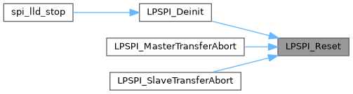
| void | LPSPI_Reset (LPSPI_Type *base) |
| Restores the LPSPI peripheral to reset state. Note that this function sets all registers to reset state. As a result, the LPSPI module can't work after calling this API. | |
| static void | LPSPI_Enable (LPSPI_Type *base, bool enable) |
| Enables the LPSPI peripheral and sets the MCR MDIS to 0. | |
Status | |
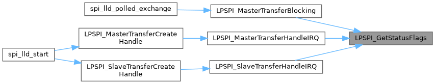
| static uint32_t | LPSPI_GetStatusFlags (LPSPI_Type *base) |
| Gets the LPSPI status flag state. | |
| static uint32_t | LPSPI_GetTxFifoSize (LPSPI_Type *base) |
| Gets the LPSPI Tx FIFO size. | |
| static uint32_t | LPSPI_GetRxFifoSize (LPSPI_Type *base) |
| Gets the LPSPI Rx FIFO size. | |
| static uint32_t | LPSPI_GetTxFifoCount (LPSPI_Type *base) |
| Gets the LPSPI Tx FIFO count. | |
| static uint32_t | LPSPI_GetRxFifoCount (LPSPI_Type *base) |
| Gets the LPSPI Rx FIFO count. | |
| static void | LPSPI_ClearStatusFlags (LPSPI_Type *base, uint32_t statusFlags) |
| Clears the LPSPI status flag. | |
Interrupts | |
| static void | LPSPI_EnableInterrupts (LPSPI_Type *base, uint32_t mask) |
| Enables the LPSPI interrupts. | |
| static void | LPSPI_DisableInterrupts (LPSPI_Type *base, uint32_t mask) |
| Disables the LPSPI interrupts. | |
DMA Control | |
| static void | LPSPI_EnableDMA (LPSPI_Type *base, uint32_t mask) |
| Enables the LPSPI DMA request. | |
| static void | LPSPI_DisableDMA (LPSPI_Type *base, uint32_t mask) |
| Disables the LPSPI DMA request. | |
| static uint32_t | LPSPI_GetTxRegisterAddress (LPSPI_Type *base) |
| Gets the LPSPI Transmit Data Register address for a DMA operation. | |
| static uint32_t | LPSPI_GetRxRegisterAddress (LPSPI_Type *base) |
| Gets the LPSPI Receive Data Register address for a DMA operation. | |
Bus Operations | |
| bool | LPSPI_CheckTransferArgument (lpspi_transfer_t *transfer, uint32_t bitsPerFrame, uint32_t bytesPerFrame) |
| Check the argument for transfer . | |
| static void | LPSPI_SetMasterSlaveMode (LPSPI_Type *base, lpspi_master_slave_mode_t mode) |
| Configures the LPSPI for either master or slave. | |
| static bool | LPSPI_IsMaster (LPSPI_Type *base) |
| Returns whether the LPSPI module is in master mode. | |
| static void | LPSPI_FlushFifo (LPSPI_Type *base, bool flushTxFifo, bool flushRxFifo) |
| Flushes the LPSPI FIFOs. | |
| static void | LPSPI_SetFifoWatermarks (LPSPI_Type *base, uint32_t txWater, uint32_t rxWater) |
| Sets the transmit and receive FIFO watermark values. | |
| static void | LPSPI_SetAllPcsPolarity (LPSPI_Type *base, uint32_t mask) |
| Configures all LPSPI peripheral chip select polarities simultaneously. | |
| static void | LPSPI_SetFrameSize (LPSPI_Type *base, uint32_t frameSize) |
| Configures the frame size. | |
| uint32_t | LPSPI_MasterSetBaudRate (LPSPI_Type *base, uint32_t baudRate_Bps, uint32_t srcClock_Hz, uint32_t *tcrPrescaleValue) |
| Sets the LPSPI baud rate in bits per second. | |
| void | LPSPI_MasterSetDelayScaler (LPSPI_Type *base, uint32_t scaler, lpspi_delay_type_t whichDelay) |
| Manually configures a specific LPSPI delay parameter (module must be disabled to change the delay values). | |
| uint32_t | LPSPI_MasterSetDelayTimes (LPSPI_Type *base, uint32_t delayTimeInNanoSec, lpspi_delay_type_t whichDelay, uint32_t srcClock_Hz) |
| Calculates the delay based on the desired delay input in nanoseconds (module must be disabled to change the delay values). | |
| static void | LPSPI_WriteData (LPSPI_Type *base, uint32_t data) |
| Writes data into the transmit data buffer. | |
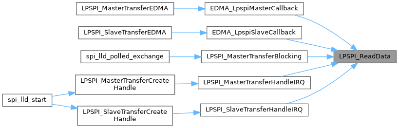
| static uint32_t | LPSPI_ReadData (LPSPI_Type *base) |
| Reads data from the data buffer. | |
| void | LPSPI_SetDummyData (LPSPI_Type *base, uint8_t dummyData) |
| Set up the dummy data. | |
Transactional | |
| void | LPSPI_MasterTransferCreateHandle (LPSPI_Type *base, lpspi_master_handle_t *handle, lpspi_master_transfer_callback_t callback, void *userData) |
| Initializes the LPSPI master handle. | |
| status_t | LPSPI_MasterTransferBlocking (LPSPI_Type *base, lpspi_transfer_t *transfer) |
| LPSPI master transfer data using a polling method. | |
| status_t | LPSPI_MasterTransferNonBlocking (LPSPI_Type *base, lpspi_master_handle_t *handle, lpspi_transfer_t *transfer) |
| LPSPI master transfer data using an interrupt method. | |
| status_t | LPSPI_MasterTransferGetCount (LPSPI_Type *base, lpspi_master_handle_t *handle, size_t *count) |
| Gets the master transfer remaining bytes. | |
| void | LPSPI_MasterTransferAbort (LPSPI_Type *base, lpspi_master_handle_t *handle) |
| LPSPI master abort transfer which uses an interrupt method. | |
| void | LPSPI_MasterTransferHandleIRQ (LPSPI_Type *base, lpspi_master_handle_t *handle) |
| LPSPI Master IRQ handler function. | |
| void | LPSPI_SlaveTransferCreateHandle (LPSPI_Type *base, lpspi_slave_handle_t *handle, lpspi_slave_transfer_callback_t callback, void *userData) |
| Initializes the LPSPI slave handle. | |
| status_t | LPSPI_SlaveTransferNonBlocking (LPSPI_Type *base, lpspi_slave_handle_t *handle, lpspi_transfer_t *transfer) |
| LPSPI slave transfer data using an interrupt method. | |
| status_t | LPSPI_SlaveTransferGetCount (LPSPI_Type *base, lpspi_slave_handle_t *handle, size_t *count) |
| Gets the slave transfer remaining bytes. | |
| void | LPSPI_SlaveTransferAbort (LPSPI_Type *base, lpspi_slave_handle_t *handle) |
| LPSPI slave aborts a transfer which uses an interrupt method. | |
| void | LPSPI_SlaveTransferHandleIRQ (LPSPI_Type *base, lpspi_slave_handle_t *handle) |
| LPSPI Slave IRQ handler function. | |
Detailed Description
Typedef Documentation
◆ lpspi_clock_phase_t
| typedef enum _lpspi_clock_phase lpspi_clock_phase_t |
LPSPI clock phase configuration.
◆ lpspi_clock_polarity_t
| typedef enum _lpspi_clock_polarity lpspi_clock_polarity_t |
LPSPI clock polarity configuration.
◆ lpspi_data_out_config_t
| typedef enum _lpspi_data_out_config lpspi_data_out_config_t |
LPSPI data output configuration.
◆ lpspi_delay_type_t
| typedef enum _lpspi_delay_type lpspi_delay_type_t |
LPSPI delay type selection.
◆ lpspi_host_request_select_t
| typedef enum _lpspi_host_request_select lpspi_host_request_select_t |
LPSPI Host Request select configuration.
◆ lpspi_master_config_t
| typedef struct _lpspi_master_config lpspi_master_config_t |
LPSPI master configuration structure.
◆ lpspi_master_handle_t
| typedef struct _lpspi_master_handle lpspi_master_handle_t |
Forward declaration of the _lpspi_master_handle typedefs.
Definition at line 302 of file fsl_lpspi.h.
◆ lpspi_master_slave_mode_t
| typedef enum _lpspi_master_slave_mode lpspi_master_slave_mode_t |
LPSPI master or slave mode configuration.
◆ lpspi_master_transfer_callback_t
| typedef void(* lpspi_master_transfer_callback_t) (LPSPI_Type *base, lpspi_master_handle_t *handle, status_t status, void *userData) |
Master completion callback function pointer type.
- Parameters
-
base LPSPI peripheral address. handle Pointer to the handle for the LPSPI master. status Success or error code describing whether the transfer is completed. userData Arbitrary pointer-dataSized value passed from the application.
Definition at line 317 of file fsl_lpspi.h.
◆ lpspi_match_config_t
| typedef enum _lpspi_match_config lpspi_match_config_t |
LPSPI Match configuration options.
◆ lpspi_pcs_polarity_config_t
| typedef enum _lpspi_pcs_polarity_config lpspi_pcs_polarity_config_t |
LPSPI Peripheral Chip Select (PCS) Polarity configuration.
◆ lpspi_pin_config_t
| typedef enum _lpspi_pin_config lpspi_pin_config_t |
LPSPI pin (SDO and SDI) configuration.
◆ lpspi_shift_direction_t
| typedef enum _lpspi_shift_direction lpspi_shift_direction_t |
LPSPI data shifter direction options.
◆ lpspi_slave_config_t
| typedef struct _lpspi_slave_config lpspi_slave_config_t |
LPSPI slave configuration structure.
◆ lpspi_slave_handle_t
| typedef struct _lpspi_slave_handle lpspi_slave_handle_t |
Forward declaration of the _lpspi_slave_handle typedefs.
Definition at line 307 of file fsl_lpspi.h.
◆ lpspi_slave_transfer_callback_t
| typedef void(* lpspi_slave_transfer_callback_t) (LPSPI_Type *base, lpspi_slave_handle_t *handle, status_t status, void *userData) |
Slave completion callback function pointer type.
- Parameters
-
base LPSPI peripheral address. handle Pointer to the handle for the LPSPI slave. status Success or error code describing whether the transfer is completed. userData Arbitrary pointer-dataSized value passed from the application.
Definition at line 330 of file fsl_lpspi.h.
◆ lpspi_transfer_t
| typedef struct _lpspi_transfer lpspi_transfer_t |
LPSPI master/slave transfer structure.
◆ lpspi_transfer_width_t
| typedef enum _lpspi_transfer_width lpspi_transfer_width_t |
LPSPI transfer width configuration.
◆ lpspi_which_pcs_t
| typedef enum _lpspi_which_pcs_config lpspi_which_pcs_t |
LPSPI Peripheral Chip Select (PCS) configuration (which PCS to configure).
Enumeration Type Documentation
◆ _lpspi_clock_phase
| enum _lpspi_clock_phase |
LPSPI clock phase configuration.
Definition at line 126 of file fsl_lpspi.h.
◆ _lpspi_clock_polarity
LPSPI clock polarity configuration.
| Enumerator | |
|---|---|
| kLPSPI_ClockPolarityActiveHigh | CPOL=0. Active-high LPSPI clock (idles low) |
| kLPSPI_ClockPolarityActiveLow | CPOL=1. Active-low LPSPI clock (idles high) |
Definition at line 119 of file fsl_lpspi.h.
◆ _lpspi_data_out_config
LPSPI data output configuration.
| Enumerator | |
|---|---|
| kLpspiDataOutRetained | Data out retains last value when chip select is de-asserted |
| kLpspiDataOutTristate | Data out is tristated when chip select is de-asserted |
Definition at line 170 of file fsl_lpspi.h.
◆ _lpspi_delay_type
| enum _lpspi_delay_type |
LPSPI delay type selection.
| Enumerator | |
|---|---|
| kLPSPI_PcsToSck | PCS-to-SCK delay. |
| kLPSPI_LastSckToPcs | Last SCK edge to PCS delay. |
| kLPSPI_BetweenTransfer | Delay between transfers. |
Definition at line 185 of file fsl_lpspi.h.
◆ _lpspi_dma_enable
| enum _lpspi_dma_enable |
LPSPI DMA source.
| Enumerator | |
|---|---|
| kLPSPI_TxDmaEnable | Transmit data DMA enable |
| kLPSPI_RxDmaEnable | Receive data DMA enable |
Definition at line 79 of file fsl_lpspi.h.
◆ _lpspi_flags
| enum _lpspi_flags |
LPSPI status flags in SPIx_SR register.
Definition at line 46 of file fsl_lpspi.h.
◆ _lpspi_host_request_select
LPSPI Host Request select configuration.
| Enumerator | |
|---|---|
| kLPSPI_HostReqExtPin | Host Request is an ext pin. |
| kLPSPI_HostReqInternalTrigger | Host Request is an internal trigger. |
Definition at line 142 of file fsl_lpspi.h.
◆ _lpspi_interrupt_enable
LPSPI interrupt source.
Definition at line 63 of file fsl_lpspi.h.
◆ _lpspi_master_slave_mode
LPSPI master or slave mode configuration.
| Enumerator | |
|---|---|
| kLPSPI_Master | LPSPI peripheral operates in master mode. |
| kLPSPI_Slave | LPSPI peripheral operates in slave mode. |
Definition at line 86 of file fsl_lpspi.h.
◆ _lpspi_match_config
| enum _lpspi_match_config |
LPSPI Match configuration options.
Definition at line 149 of file fsl_lpspi.h.
◆ _lpspi_pcs_polarity
| enum _lpspi_pcs_polarity |
LPSPI Peripheral Chip Select (PCS) Polarity.
Definition at line 109 of file fsl_lpspi.h.
◆ _lpspi_pcs_polarity_config
LPSPI Peripheral Chip Select (PCS) Polarity configuration.
| Enumerator | |
|---|---|
| kLPSPI_PcsActiveHigh | PCS Active High (idles low) |
| kLPSPI_PcsActiveLow | PCS Active Low (idles high) |
Definition at line 102 of file fsl_lpspi.h.
◆ _lpspi_pin_config
| enum _lpspi_pin_config |
LPSPI pin (SDO and SDI) configuration.
Definition at line 161 of file fsl_lpspi.h.
◆ _lpspi_shift_direction
LPSPI data shifter direction options.
| Enumerator | |
|---|---|
| kLPSPI_MsbFirst | Data transfers start with most significant bit. |
| kLPSPI_LsbFirst | Data transfers start with least significant bit. |
Definition at line 135 of file fsl_lpspi.h.
◆ _lpspi_status
| enum _lpspi_status |
Status for the LPSPI driver.
| Enumerator | |
|---|---|
| kStatus_LPSPI_Busy | LPSPI transfer is busy. |
| kStatus_LPSPI_Error | LPSPI driver error. |
| kStatus_LPSPI_Idle | LPSPI is idle. |
| kStatus_LPSPI_OutOfRange | LPSPI transfer out Of range. |
Definition at line 37 of file fsl_lpspi.h.
◆ _lpspi_transfer_config_flag_for_master
Use this enumeration for LPSPI master transfer configFlags.
Definition at line 196 of file fsl_lpspi.h.
◆ _lpspi_transfer_config_flag_for_slave
Use this enumeration for LPSPI slave transfer configFlags.
Definition at line 224 of file fsl_lpspi.h.
◆ _lpspi_transfer_state
LPSPI transfer state, which is used for LPSPI transactional API state machine.
| Enumerator | |
|---|---|
| kLPSPI_Idle | Nothing in the transmitter/receiver. |
| kLPSPI_Busy | Transfer queue is not finished. |
| kLPSPI_Error | Transfer error. |
Definition at line 247 of file fsl_lpspi.h.
◆ _lpspi_transfer_width
LPSPI transfer width configuration.
Definition at line 177 of file fsl_lpspi.h.
◆ _lpspi_which_pcs_config
LPSPI Peripheral Chip Select (PCS) configuration (which PCS to configure).
| Enumerator | |
|---|---|
| kLPSPI_Pcs0 | PCS[0] |
| kLPSPI_Pcs1 | PCS[1] |
| kLPSPI_Pcs2 | PCS[2] |
| kLPSPI_Pcs3 | PCS[3] |
Definition at line 93 of file fsl_lpspi.h.
Function Documentation
◆ LPSPI_CheckTransferArgument()
| bool LPSPI_CheckTransferArgument | ( | lpspi_transfer_t * | transfer, |
| uint32_t | bitsPerFrame, | ||
| uint32_t | bytesPerFrame | ||
| ) |
Check the argument for transfer .
- Parameters
-
transfer the transfer struct to be used. bitPerFrame The bit size of one frame. bytePerFrame The byte size of one frame.
- Returns
- Return true for right and false for wrong.
brief Check the argument for transfer .
param transfer the transfer struct to be used. param bitPerFrame The bit size of one frame. param bytePerFrame The byte size of one frame. return Return true for right and false for wrong.
Definition at line 713 of file fsl_lpspi.c.
Referenced by LPSPI_MasterTransferBlocking(), LPSPI_MasterTransferEDMA(), LPSPI_MasterTransferNonBlocking(), LPSPI_SlaveTransferEDMA(), and LPSPI_SlaveTransferNonBlocking().

◆ LPSPI_ClearStatusFlags()
|
inlinestatic |
Clears the LPSPI status flag.
This function clears the desired status bit by using a write-1-to-clear. The user passes in the base and the desired status flag bit to clear. The list of status flags is defined in the _lpspi_flags. Example usage:
- Parameters
-
base LPSPI peripheral address. statusFlags The status flag used from type _lpspi_flags.
< The status flags are cleared by writing 1 (w1c).
Definition at line 575 of file fsl_lpspi.h.
Referenced by LPSPI_MasterTransferBlocking(), LPSPI_MasterTransferEDMA(), LPSPI_MasterTransferNonBlocking(), LPSPI_SlaveTransferEDMA(), LPSPI_SlaveTransferHandleIRQ(), and LPSPI_SlaveTransferNonBlocking().

◆ LPSPI_Deinit()
| void LPSPI_Deinit | ( | LPSPI_Type * | base | ) |
De-initializes the LPSPI peripheral. Call this API to disable the LPSPI clock.
- Parameters
-
base LPSPI peripheral address.
brief De-initializes the LPSPI peripheral. Call this API to disable the LPSPI clock. param base LPSPI peripheral address.
Definition at line 367 of file fsl_lpspi.c.
Referenced by spi_lld_stop().

◆ LPSPI_DisableDMA()
|
inlinestatic |
Disables the LPSPI DMA request.
This function configures the Rx and Tx DMA mask of the LPSPI. The parameters are base and a DMA mask.
- Parameters
-
base LPSPI peripheral address. mask The interrupt mask; Use the enum _lpspi_dma_enable.
Definition at line 658 of file fsl_lpspi.h.
Referenced by EDMA_LpspiMasterCallback(), EDMA_LpspiSlaveCallback(), LPSPI_MasterTransferAbortEDMA(), LPSPI_MasterTransferEDMA(), LPSPI_SlaveTransferAbortEDMA(), and LPSPI_SlaveTransferEDMA().

◆ LPSPI_DisableInterrupts()
|
inlinestatic |
Disables the LPSPI interrupts.
- Parameters
-
base LPSPI peripheral address. mask The interrupt mask; Use the enum _lpspi_interrupt_enable.
Definition at line 617 of file fsl_lpspi.h.
Referenced by LPSPI_MasterTransferAbort(), LPSPI_MasterTransferComplete(), LPSPI_MasterTransferEDMA(), LPSPI_MasterTransferHandleIRQ(), LPSPI_MasterTransferNonBlocking(), LPSPI_SlaveTransferAbort(), LPSPI_SlaveTransferComplete(), LPSPI_SlaveTransferEDMA(), LPSPI_SlaveTransferHandleIRQ(), and LPSPI_SlaveTransferNonBlocking().

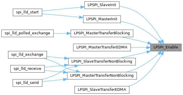
◆ LPSPI_Enable()
|
inlinestatic |
Enables the LPSPI peripheral and sets the MCR MDIS to 0.
- Parameters
-
base LPSPI peripheral address. enable Pass true to enable module, false to disable module.
Definition at line 491 of file fsl_lpspi.h.
Referenced by LPSPI_MasterInit(), LPSPI_MasterTransferBlocking(), LPSPI_MasterTransferEDMA(), LPSPI_MasterTransferNonBlocking(), LPSPI_SlaveInit(), LPSPI_SlaveTransferEDMA(), and LPSPI_SlaveTransferNonBlocking().
◆ LPSPI_EnableDMA()
|
inlinestatic |
Enables the LPSPI DMA request.
This function configures the Rx and Tx DMA mask of the LPSPI. The parameters are base and a DMA mask.
- Parameters
-
base LPSPI peripheral address. mask The interrupt mask; Use the enum _lpspi_dma_enable.
Definition at line 642 of file fsl_lpspi.h.
Referenced by LPSPI_MasterTransferEDMA(), and LPSPI_SlaveTransferEDMA().

◆ LPSPI_EnableInterrupts()
|
inlinestatic |
Enables the LPSPI interrupts.
This function configures the various interrupt masks of the LPSPI. The parameters are base and an interrupt mask. Note that, for Tx fill and Rx FIFO drain requests, enabling the interrupt request disables the DMA request.
- Parameters
-
base LPSPI peripheral address. mask The interrupt mask; Use the enum _lpspi_interrupt_enable.
Definition at line 602 of file fsl_lpspi.h.
Referenced by LPSPI_MasterTransferHandleIRQ(), LPSPI_MasterTransferNonBlocking(), LPSPI_SlaveTransferHandleIRQ(), and LPSPI_SlaveTransferNonBlocking().

◆ LPSPI_FlushFifo()
Flushes the LPSPI FIFOs.
- Parameters
-
base LPSPI peripheral address. flushTxFifo Flushes (true) the Tx FIFO, else do not flush (false) the Tx FIFO. flushRxFifo Flushes (true) the Rx FIFO, else do not flush (false) the Rx FIFO.
Definition at line 743 of file fsl_lpspi.h.
Referenced by LPSPI_MasterTransferBlocking(), LPSPI_MasterTransferEDMA(), LPSPI_MasterTransferNonBlocking(), LPSPI_SlaveTransferEDMA(), and LPSPI_SlaveTransferNonBlocking().

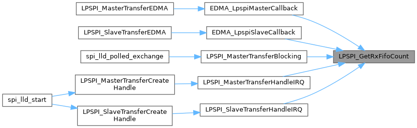
◆ LPSPI_GetRxFifoCount()
|
inlinestatic |
Gets the LPSPI Rx FIFO count.
- Parameters
-
base LPSPI peripheral address.
- Returns
- The number of words in the receive FIFO.
Definition at line 557 of file fsl_lpspi.h.
Referenced by EDMA_LpspiMasterCallback(), EDMA_LpspiSlaveCallback(), LPSPI_MasterTransferBlocking(), LPSPI_MasterTransferHandleIRQ(), and LPSPI_SlaveTransferHandleIRQ().
◆ LPSPI_GetRxFifoSize()
|
inlinestatic |
Gets the LPSPI Rx FIFO size.
- Parameters
-
base LPSPI peripheral address.
- Returns
- The LPSPI Rx FIFO size.
Definition at line 537 of file fsl_lpspi.h.
Referenced by LPSPI_MasterTransferBlocking(), LPSPI_MasterTransferEDMA(), LPSPI_MasterTransferNonBlocking(), LPSPI_SlaveTransferEDMA(), and LPSPI_SlaveTransferNonBlocking().

◆ LPSPI_GetRxRegisterAddress()
|
inlinestatic |
Gets the LPSPI Receive Data Register address for a DMA operation.
This function gets the LPSPI Receive Data Register address because this value is needed for the DMA operation. This function can be used for either master or slave mode.
- Parameters
-
base LPSPI peripheral address.
- Returns
- The LPSPI Receive Data Register address.
Definition at line 688 of file fsl_lpspi.h.
Referenced by LPSPI_MasterTransferEDMA(), and LPSPI_SlaveTransferEDMA().

◆ LPSPI_GetStatusFlags()
|
inlinestatic |
Gets the LPSPI status flag state.
- Parameters
-
base LPSPI peripheral address.
- Returns
- The LPSPI status(in SR register).
Definition at line 517 of file fsl_lpspi.h.
Referenced by LPSPI_MasterTransferBlocking(), LPSPI_MasterTransferHandleIRQ(), and LPSPI_SlaveTransferHandleIRQ().
◆ LPSPI_GetTxFifoCount()
|
inlinestatic |
Gets the LPSPI Tx FIFO count.
- Parameters
-
base LPSPI peripheral address.
- Returns
- The number of words in the transmit FIFO.
Definition at line 547 of file fsl_lpspi.h.
Referenced by LPSPI_MasterTransferBlocking(), LPSPI_MasterTransferFillUpTxFifo(), LPSPI_MasterTransferHandleIRQ(), LPSPI_MasterTransferNonBlocking(), LPSPI_SlaveTransferFillUpTxFifo(), LPSPI_SlaveTransferHandleIRQ(), and LPSPI_SlaveTransferNonBlocking().

◆ LPSPI_GetTxFifoSize()
|
inlinestatic |
Gets the LPSPI Tx FIFO size.
- Parameters
-
base LPSPI peripheral address.
- Returns
- The LPSPI Tx FIFO size.
Definition at line 527 of file fsl_lpspi.h.
◆ LPSPI_GetTxRegisterAddress()
|
inlinestatic |
Gets the LPSPI Transmit Data Register address for a DMA operation.
This function gets the LPSPI Transmit Data Register address because this value is needed for the DMA operation. This function can be used for either master or slave mode.
- Parameters
-
base LPSPI peripheral address.
- Returns
- The LPSPI Transmit Data Register address.
Definition at line 673 of file fsl_lpspi.h.
Referenced by LPSPI_MasterTransferEDMA(), and LPSPI_SlaveTransferEDMA().

◆ LPSPI_IsMaster()
|
inlinestatic |
Returns whether the LPSPI module is in master mode.
- Parameters
-
base LPSPI peripheral address.
- Returns
- Returns true if the module is in master mode or false if the module is in slave mode.
Definition at line 731 of file fsl_lpspi.h.
Referenced by LPSPI_CommonIRQHandler(), and LPSPI_MasterSetBaudRate().

◆ LPSPI_MasterGetDefaultConfig()
| void LPSPI_MasterGetDefaultConfig | ( | lpspi_master_config_t * | masterConfig | ) |
Sets the lpspi_master_config_t structure to default values.
This API initializes the configuration structure for LPSPI_MasterInit(). The initialized structure can remain unchanged in LPSPI_MasterInit(), or can be modified before calling the LPSPI_MasterInit(). Example:
- Parameters
-
masterConfig pointer to lpspi_master_config_t structure
brief Sets the lpspi_master_config_t structure to default values.
This API initializes the configuration structure for LPSPI_MasterInit(). The initialized structure can remain unchanged in LPSPI_MasterInit(), or can be modified before calling the LPSPI_MasterInit(). Example: code lpspi_master_config_t masterConfig; LPSPI_MasterGetDefaultConfig(&masterConfig); endcode param masterConfig pointer to lpspi_master_config_t structure
Definition at line 249 of file fsl_lpspi.c.
Referenced by spi_lld_start().

◆ LPSPI_MasterInit()
| void LPSPI_MasterInit | ( | LPSPI_Type * | base, |
| const lpspi_master_config_t * | masterConfig, | ||
| uint32_t | srcClock_Hz | ||
| ) |
Initializes the LPSPI master.
- Parameters
-
base LPSPI peripheral address. masterConfig Pointer to structure lpspi_master_config_t. srcClock_Hz Module source input clock in Hertz
brief Initializes the LPSPI master.
param base LPSPI peripheral address. param masterConfig Pointer to structure lpspi_master_config_t. param srcClock_Hz Module source input clock in Hertz
Definition at line 187 of file fsl_lpspi.c.
Referenced by spi_lld_start().


◆ LPSPI_MasterSetBaudRate()
| uint32_t LPSPI_MasterSetBaudRate | ( | LPSPI_Type * | base, |
| uint32_t | baudRate_Bps, | ||
| uint32_t | srcClock_Hz, | ||
| uint32_t * | tcrPrescaleValue | ||
| ) |
Sets the LPSPI baud rate in bits per second.
This function takes in the desired bitsPerSec (baud rate) and calculates the nearest possible baud rate without exceeding the desired baud rate and returns the calculated baud rate in bits-per-second. It requires the caller to provide the frequency of the module source clock (in Hertz). Note that the baud rate does not go into effect until the Transmit Control Register (TCR) is programmed with the prescale value. Hence, this function returns the prescale tcrPrescaleValue parameter for later programming in the TCR. The higher level peripheral driver should alert the user of an out of range baud rate input.
Note that the LPSPI module must first be disabled before configuring this. Note that the LPSPI module must be configured for master mode before configuring this.
- Parameters
-
base LPSPI peripheral address. baudRate_Bps The desired baud rate in bits per second. srcClock_Hz Module source input clock in Hertz. tcrPrescaleValue The TCR prescale value needed to program the TCR.
- Returns
- The actual calculated baud rate. This function may also return a "0" if the LPSPI is not configured for master mode or if the LPSPI module is not disabled.
brief Sets the LPSPI baud rate in bits per second.
This function takes in the desired bitsPerSec (baud rate) and calculates the nearest possible baud rate without exceeding the desired baud rate and returns the calculated baud rate in bits-per-second. It requires the caller to provide the frequency of the module source clock (in Hertz). Note that the baud rate does not go into effect until the Transmit Control Register (TCR) is programmed with the prescale value. Hence, this function returns the prescale tcrPrescaleValue parameter for later programming in the TCR. The higher level peripheral driver should alert the user of an out of range baud rate input.
Note that the LPSPI module must first be disabled before configuring this. Note that the LPSPI module must be configured for master mode before configuring this.
param base LPSPI peripheral address. param baudRate_Bps The desired baud rate in bits per second. param srcClock_Hz Module source input clock in Hertz. param tcrPrescaleValue The TCR prescale value needed to program the TCR. return The actual calculated baud rate. This function may also return a "0" if the LPSPI is not configured for master mode or if the LPSPI module is not disabled.
Definition at line 420 of file fsl_lpspi.c.
Referenced by LPSPI_MasterInit().


◆ LPSPI_MasterSetDelayScaler()
| void LPSPI_MasterSetDelayScaler | ( | LPSPI_Type * | base, |
| uint32_t | scaler, | ||
| lpspi_delay_type_t | whichDelay | ||
| ) |
Manually configures a specific LPSPI delay parameter (module must be disabled to change the delay values).
This function configures the following: SCK to PCS delay, or PCS to SCK delay, or The configurations must occur between the transfer delay.
The delay names are available in type lpspi_delay_type_t.
The user passes the desired delay along with the delay value. This allows the user to directly set the delay values if they have pre-calculated them or if they simply wish to manually increment the value.
Note that the LPSPI module must first be disabled before configuring this. Note that the LPSPI module must be configured for master mode before configuring this.
- Parameters
-
base LPSPI peripheral address. scaler The 8-bit delay value 0x00 to 0xFF (255). whichDelay The desired delay to configure, must be of type lpspi_delay_type_t.
brief Manually configures a specific LPSPI delay parameter (module must be disabled to change the delay values).
This function configures the following: SCK to PCS delay, or PCS to SCK delay, or The configurations must occur between the transfer delay.
The delay names are available in type lpspi_delay_type_t.
The user passes the desired delay along with the delay value. This allows the user to directly set the delay values if they have pre-calculated them or if they simply wish to manually increment the value.
Note that the LPSPI module must first be disabled before configuring this. Note that the LPSPI module must be configured for master mode before configuring this.
param base LPSPI peripheral address. param scaler The 8-bit delay value 0x00 to 0xFF (255). param whichDelay The desired delay to configure, must be of type lpspi_delay_type_t.
Definition at line 516 of file fsl_lpspi.c.
Referenced by LPSPI_MasterSetDelayTimes().

◆ LPSPI_MasterSetDelayTimes()
| uint32_t LPSPI_MasterSetDelayTimes | ( | LPSPI_Type * | base, |
| uint32_t | delayTimeInNanoSec, | ||
| lpspi_delay_type_t | whichDelay, | ||
| uint32_t | srcClock_Hz | ||
| ) |
Calculates the delay based on the desired delay input in nanoseconds (module must be disabled to change the delay values).
This function calculates the values for the following: SCK to PCS delay, or PCS to SCK delay, or The configurations must occur between the transfer delay.
The delay names are available in type lpspi_delay_type_t.
The user passes the desired delay and the desired delay value in nano-seconds. The function calculates the value needed for the desired delay parameter and returns the actual calculated delay because an exact delay match may not be possible. In this case, the closest match is calculated without going below the desired delay value input. It is possible to input a very large delay value that exceeds the capability of the part, in which case the maximum supported delay is returned. It is up to the higher level peripheral driver to alert the user of an out of range delay input.
Note that the LPSPI module must be configured for master mode before configuring this. And note that the delayTime = LPSPI_clockSource / (PRESCALE * Delay_scaler).
- Parameters
-
base LPSPI peripheral address. delayTimeInNanoSec The desired delay value in nano-seconds. whichDelay The desired delay to configuration, which must be of type lpspi_delay_type_t. srcClock_Hz Module source input clock in Hertz.
- Returns
- actual Calculated delay value in nano-seconds.
brief Calculates the delay based on the desired delay input in nanoseconds (module must be disabled to change the delay values).
This function calculates the values for the following: SCK to PCS delay, or PCS to SCK delay, or The configurations must occur between the transfer delay.
The delay names are available in type lpspi_delay_type_t.
The user passes the desired delay and the desired delay value in nano-seconds. The function calculates the value needed for the desired delay parameter and returns the actual calculated delay because an exact delay match may not be possible. In this case, the closest match is calculated without going below the desired delay value input. It is possible to input a very large delay value that exceeds the capability of the part, in which case the maximum supported delay is returned. It is up to the higher level peripheral driver to alert the user of an out of range delay input.
Note that the LPSPI module must be configured for master mode before configuring this. And note that the delayTime = LPSPI_clockSource / (PRESCALE * Delay_scaler).
param base LPSPI peripheral address. param delayTimeInNanoSec The desired delay value in nano-seconds. param whichDelay The desired delay to configuration, which must be of type lpspi_delay_type_t. param srcClock_Hz Module source input clock in Hertz. return actual Calculated delay value in nano-seconds.
Definition at line 567 of file fsl_lpspi.c.
Referenced by LPSPI_MasterInit().


◆ LPSPI_MasterTransferAbort()
| void LPSPI_MasterTransferAbort | ( | LPSPI_Type * | base, |
| lpspi_master_handle_t * | handle | ||
| ) |
LPSPI master abort transfer which uses an interrupt method.
This function aborts a transfer which uses an interrupt method.
- Parameters
-
base LPSPI peripheral address. handle pointer to lpspi_master_handle_t structure which stores the transfer state.
brief LPSPI master abort transfer which uses an interrupt method.
This function aborts a transfer which uses an interrupt method.
param base LPSPI peripheral address. param handle pointer to lpspi_master_handle_t structure which stores the transfer state.
Definition at line 1235 of file fsl_lpspi.c.

◆ LPSPI_MasterTransferBlocking()
| status_t LPSPI_MasterTransferBlocking | ( | LPSPI_Type * | base, |
| lpspi_transfer_t * | transfer | ||
| ) |
LPSPI master transfer data using a polling method.
This function transfers data using a polling method. This is a blocking function, which does not return until all transfers have been completed.
Note: The transfer data size should be integer multiples of bytesPerFrame if bytesPerFrame is less than or equal to 4. For bytesPerFrame greater than 4: The transfer data size should be equal to bytesPerFrame if the bytesPerFrame is not integer multiples of 4. Otherwise, the transfer data size can be an integer multiple of bytesPerFrame.
- Parameters
-
base LPSPI peripheral address. transfer pointer to lpspi_transfer_t structure.
- Returns
- status of status_t.
brief LPSPI master transfer data using a polling method.
This function transfers data using a polling method. This is a blocking function, which does not return until all transfers have been completed.
Note: The transfer data size should be integer multiples of bytesPerFrame if bytesPerFrame is less than or equal to 4. For bytesPerFrame greater than 4: The transfer data size should be equal to bytesPerFrame if the bytesPerFrame is not integer multiples of 4. Otherwise, the transfer data size can be an integer multiple of bytesPerFrame.
param base LPSPI peripheral address. param transfer pointer to lpspi_transfer_t structure. return status of status_t.
Definition at line 779 of file fsl_lpspi.c.
Referenced by spi_lld_polled_exchange().


◆ LPSPI_MasterTransferCreateHandle()
| void LPSPI_MasterTransferCreateHandle | ( | LPSPI_Type * | base, |
| lpspi_master_handle_t * | handle, | ||
| lpspi_master_transfer_callback_t | callback, | ||
| void * | userData | ||
| ) |
Initializes the LPSPI master handle.
This function initializes the LPSPI handle, which can be used for other LPSPI transactional APIs. Usually, for a specified LPSPI instance, call this API once to get the initialized handle.
- Parameters
-
base LPSPI peripheral address. handle LPSPI handle pointer to lpspi_master_handle_t. callback DSPI callback. userData callback function parameter.
brief Initializes the LPSPI master handle.
This function initializes the LPSPI handle, which can be used for other LPSPI transactional APIs. Usually, for a specified LPSPI instance, call this API once to get the initialized handle.
param base LPSPI peripheral address. param handle LPSPI handle pointer to lpspi_master_handle_t. param callback DSPI callback. param userData callback function parameter.
Definition at line 686 of file fsl_lpspi.c.
Referenced by spi_lld_start().


◆ LPSPI_MasterTransferGetCount()
| status_t LPSPI_MasterTransferGetCount | ( | LPSPI_Type * | base, |
| lpspi_master_handle_t * | handle, | ||
| size_t * | count | ||
| ) |
Gets the master transfer remaining bytes.
This function gets the master transfer remaining bytes.
- Parameters
-
base LPSPI peripheral address. handle pointer to lpspi_master_handle_t structure which stores the transfer state. count Number of bytes transferred so far by the non-blocking transaction.
- Returns
- status of status_t.
brief Gets the master transfer remaining bytes.
This function gets the master transfer remaining bytes.
param base LPSPI peripheral address. param handle pointer to lpspi_master_handle_t structure which stores the transfer state. param count Number of bytes transferred so far by the non-blocking transaction. return status of status_t.
Definition at line 1195 of file fsl_lpspi.c.
◆ LPSPI_MasterTransferHandleIRQ()
| void LPSPI_MasterTransferHandleIRQ | ( | LPSPI_Type * | base, |
| lpspi_master_handle_t * | handle | ||
| ) |
LPSPI Master IRQ handler function.
This function processes the LPSPI transmit and receive IRQ.
- Parameters
-
base LPSPI peripheral address. handle pointer to lpspi_master_handle_t structure which stores the transfer state.
brief LPSPI Master IRQ handler function.
This function processes the LPSPI transmit and receive IRQ.
param base LPSPI peripheral address. param handle pointer to lpspi_master_handle_t structure which stores the transfer state.
Definition at line 1257 of file fsl_lpspi.c.
Referenced by LPSPI_MasterTransferCreateHandle().


◆ LPSPI_MasterTransferNonBlocking()
| status_t LPSPI_MasterTransferNonBlocking | ( | LPSPI_Type * | base, |
| lpspi_master_handle_t * | handle, | ||
| lpspi_transfer_t * | transfer | ||
| ) |
LPSPI master transfer data using an interrupt method.
This function transfers data using an interrupt method. This is a non-blocking function, which returns right away. When all data is transferred, the callback function is called.
Note: The transfer data size should be integer multiples of bytesPerFrame if bytesPerFrame is less than or equal to 4. For bytesPerFrame greater than 4: The transfer data size should be equal to bytesPerFrame if the bytesPerFrame is not integer multiples of 4. Otherwise, the transfer data size can be an integer multiple of bytesPerFrame.
- Parameters
-
base LPSPI peripheral address. handle pointer to lpspi_master_handle_t structure which stores the transfer state. transfer pointer to lpspi_transfer_t structure.
- Returns
- status of status_t.
brief LPSPI master transfer data using an interrupt method.
This function transfers data using an interrupt method. This is a non-blocking function, which returns right away. When all data is transferred, the callback function is called.
Note: The transfer data size should be integer multiples of bytesPerFrame if bytesPerFrame is less than or equal to 4. For bytesPerFrame greater than 4: The transfer data size should be equal to bytesPerFrame if the bytesPerFrame is not integer multiples of 4. Otherwise, the transfer data size can be an integer multiple of bytesPerFrame.
param base LPSPI peripheral address. param handle pointer to lpspi_master_handle_t structure which stores the transfer state. param transfer pointer to lpspi_transfer_t structure. return status of status_t.
Definition at line 961 of file fsl_lpspi.c.
Referenced by spi_lld_exchange(), spi_lld_receive(), and spi_lld_send().


◆ LPSPI_ReadData()
|
inlinestatic |
Reads data from the data buffer.
This function reads the data from the Receive Data Register (RDR). This function can be used for either master or slave mode.
- Parameters
-
base LPSPI peripheral address.
- Returns
- The data read from the data buffer.
Definition at line 918 of file fsl_lpspi.h.
Referenced by EDMA_LpspiMasterCallback(), EDMA_LpspiSlaveCallback(), LPSPI_MasterTransferBlocking(), LPSPI_MasterTransferHandleIRQ(), and LPSPI_SlaveTransferHandleIRQ().
◆ LPSPI_Reset()
| void LPSPI_Reset | ( | LPSPI_Type * | base | ) |
Restores the LPSPI peripheral to reset state. Note that this function sets all registers to reset state. As a result, the LPSPI module can't work after calling this API.
- Parameters
-
base LPSPI peripheral address.
brief Restores the LPSPI peripheral to reset state. Note that this function sets all registers to reset state. As a result, the LPSPI module can't work after calling this API. param base LPSPI peripheral address.
Definition at line 351 of file fsl_lpspi.c.
Referenced by LPSPI_Deinit(), LPSPI_MasterTransferAbort(), and LPSPI_SlaveTransferAbort().
◆ LPSPI_SetAllPcsPolarity()
|
inlinestatic |
Configures all LPSPI peripheral chip select polarities simultaneously.
Note that the CFGR1 should only be written when the LPSPI is disabled (LPSPIx_CR_MEN = 0).
This is an example: PCS0 and PCS1 set to active low and other PCSs set to active high. Note that the number of PCS is device-specific.
- Parameters
-
base LPSPI peripheral address. mask The PCS polarity mask; Use the enum _lpspi_pcs_polarity.
Definition at line 778 of file fsl_lpspi.h.
◆ LPSPI_SetDummyData()
| void LPSPI_SetDummyData | ( | LPSPI_Type * | base, |
| uint8_t | dummyData | ||
| ) |
Set up the dummy data.
- Parameters
-
base LPSPI peripheral address. dummyData Data to be transferred when tx buffer is NULL. Note: This API has no effect when LPSPI in slave interrupt mode, because driver will set the TXMSK bit to 1 if txData is NULL, no data is loaded from transmit FIFO and output pin is tristated.
brief Set up the dummy data.
param base LPSPI peripheral address. param dummyData Data to be transferred when tx buffer is NULL. Note: This API has no effect when LPSPI in slave interrupt mode, because driver will set the TXMSK bit to 1 if txData is NULL, no data is loaded from transmit FIFO and output pin is tristated.
Definition at line 174 of file fsl_lpspi.c.
Referenced by LPSPI_MasterInit(), and LPSPI_SlaveInit().


◆ LPSPI_SetFifoWatermarks()
|
inlinestatic |
Sets the transmit and receive FIFO watermark values.
This function allows the user to set the receive and transmit FIFO watermarks. The function does not compare the watermark settings to the FIFO size. The FIFO watermark should not be equal to or greater than the FIFO size. It is up to the higher level driver to make this check.
- Parameters
-
base LPSPI peripheral address. txWater The TX FIFO watermark value. Writing a value equal or greater than the FIFO size is truncated. rxWater The RX FIFO watermark value. Writing a value equal or greater than the FIFO size is truncated.
Definition at line 759 of file fsl_lpspi.h.
Referenced by LPSPI_MasterInit(), LPSPI_MasterTransferEDMA(), LPSPI_MasterTransferNonBlocking(), LPSPI_SlaveInit(), LPSPI_SlaveTransferEDMA(), and LPSPI_SlaveTransferNonBlocking().

◆ LPSPI_SetFrameSize()
|
inlinestatic |
Configures the frame size.
The minimum frame size is 8-bits and the maximum frame size is 4096-bits. If the frame size is less than or equal to 32-bits, the word size and frame size are identical. If the frame size is greater than 32-bits, the word size is 32-bits for each word except the last (the last word contains the remainder bits if the frame size is not divisible by 32). The minimum word size is 2-bits. A frame size of 33-bits (or similar) is not supported.
Note 1: The transmit command register should be initialized before enabling the LPSPI in slave mode, although the command register does not update until after the LPSPI is enabled. After it is enabled, the transmit command register should only be changed if the LPSPI is idle.
Note 2: The transmit and command FIFO is a combined FIFO that includes both transmit data and command words. That means the TCR register should be written to when the Tx FIFO is not full.
- Parameters
-
base LPSPI peripheral address. frameSize The frame size in number of bits.
Definition at line 802 of file fsl_lpspi.h.
◆ LPSPI_SetMasterSlaveMode()
|
inlinestatic |
Configures the LPSPI for either master or slave.
Note that the CFGR1 should only be written when the LPSPI is disabled (LPSPIx_CR_MEN = 0).
- Parameters
-
base LPSPI peripheral address. mode Mode setting (master or slave) of type lpspi_master_slave_mode_t.
Definition at line 720 of file fsl_lpspi.h.
Referenced by LPSPI_MasterInit(), and LPSPI_SlaveInit().

◆ LPSPI_SlaveGetDefaultConfig()
| void LPSPI_SlaveGetDefaultConfig | ( | lpspi_slave_config_t * | slaveConfig | ) |
Sets the lpspi_slave_config_t structure to default values.
This API initializes the configuration structure for LPSPI_SlaveInit(). The initialized structure can remain unchanged in LPSPI_SlaveInit() or can be modified before calling the LPSPI_SlaveInit(). Example:
- Parameters
-
slaveConfig pointer to lpspi_slave_config_t structure.
brief Sets the lpspi_slave_config_t structure to default values.
This API initializes the configuration structure for LPSPI_SlaveInit(). The initialized structure can remain unchanged in LPSPI_SlaveInit() or can be modified before calling the LPSPI_SlaveInit(). Example: code lpspi_slave_config_t slaveConfig; LPSPI_SlaveGetDefaultConfig(&slaveConfig); endcode param slaveConfig pointer to lpspi_slave_config_t structure.
< Bits per frame, minimum 8, maximum 4096.
< Clock polarity.
< Clock phase.
< MSB or LSB data shift direction.
< Desired Peripheral Chip Select (pcs)
< Desired PCS active high or low
Definition at line 326 of file fsl_lpspi.c.
Referenced by spi_lld_start().

◆ LPSPI_SlaveInit()
| void LPSPI_SlaveInit | ( | LPSPI_Type * | base, |
| const lpspi_slave_config_t * | slaveConfig | ||
| ) |
LPSPI slave configuration.
- Parameters
-
base LPSPI peripheral address. slaveConfig Pointer to a structure lpspi_slave_config_t.
brief LPSPI slave configuration.
param base LPSPI peripheral address. param slaveConfig Pointer to a structure lpspi_slave_config_t.
Definition at line 279 of file fsl_lpspi.c.
Referenced by spi_lld_start().


◆ LPSPI_SlaveTransferAbort()
| void LPSPI_SlaveTransferAbort | ( | LPSPI_Type * | base, |
| lpspi_slave_handle_t * | handle | ||
| ) |
LPSPI slave aborts a transfer which uses an interrupt method.
This function aborts a transfer which uses an interrupt method.
- Parameters
-
base LPSPI peripheral address. handle pointer to lpspi_slave_handle_t structure which stores the transfer state.
brief LPSPI slave aborts a transfer which uses an interrupt method.
This function aborts a transfer which uses an interrupt method.
param base LPSPI peripheral address. param handle pointer to lpspi_slave_handle_t structure which stores the transfer state.
Definition at line 1669 of file fsl_lpspi.c.

◆ LPSPI_SlaveTransferCreateHandle()
| void LPSPI_SlaveTransferCreateHandle | ( | LPSPI_Type * | base, |
| lpspi_slave_handle_t * | handle, | ||
| lpspi_slave_transfer_callback_t | callback, | ||
| void * | userData | ||
| ) |
Initializes the LPSPI slave handle.
This function initializes the LPSPI handle, which can be used for other LPSPI transactional APIs. Usually, for a specified LPSPI instance, call this API once to get the initialized handle.
- Parameters
-
base LPSPI peripheral address. handle LPSPI handle pointer to lpspi_slave_handle_t. callback DSPI callback. userData callback function parameter.
brief Initializes the LPSPI slave handle.
This function initializes the LPSPI handle, which can be used for other LPSPI transactional APIs. Usually, for a specified LPSPI instance, call this API once to get the initialized handle.
param base LPSPI peripheral address. param handle LPSPI handle pointer to lpspi_slave_handle_t. param callback DSPI callback. param userData callback function parameter.
Definition at line 1366 of file fsl_lpspi.c.
Referenced by spi_lld_start().


◆ LPSPI_SlaveTransferGetCount()
| status_t LPSPI_SlaveTransferGetCount | ( | LPSPI_Type * | base, |
| lpspi_slave_handle_t * | handle, | ||
| size_t * | count | ||
| ) |
Gets the slave transfer remaining bytes.
This function gets the slave transfer remaining bytes.
- Parameters
-
base LPSPI peripheral address. handle pointer to lpspi_slave_handle_t structure which stores the transfer state. count Number of bytes transferred so far by the non-blocking transaction.
- Returns
- status of status_t.
brief Gets the slave transfer remaining bytes.
This function gets the slave transfer remaining bytes.
param base LPSPI peripheral address. param handle pointer to lpspi_slave_handle_t structure which stores the transfer state. param count Number of bytes transferred so far by the non-blocking transaction. return status of status_t.
Definition at line 1629 of file fsl_lpspi.c.
◆ LPSPI_SlaveTransferHandleIRQ()
| void LPSPI_SlaveTransferHandleIRQ | ( | LPSPI_Type * | base, |
| lpspi_slave_handle_t * | handle | ||
| ) |
LPSPI Slave IRQ handler function.
This function processes the LPSPI transmit and receives an IRQ.
- Parameters
-
base LPSPI peripheral address. handle pointer to lpspi_slave_handle_t structure which stores the transfer state.
brief LPSPI Slave IRQ handler function.
This function processes the LPSPI transmit and receives an IRQ.
param base LPSPI peripheral address. param handle pointer to lpspi_slave_handle_t structure which stores the transfer state.
Definition at line 1691 of file fsl_lpspi.c.
Referenced by LPSPI_SlaveTransferCreateHandle().


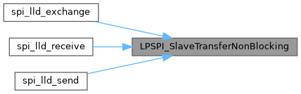
◆ LPSPI_SlaveTransferNonBlocking()
| status_t LPSPI_SlaveTransferNonBlocking | ( | LPSPI_Type * | base, |
| lpspi_slave_handle_t * | handle, | ||
| lpspi_transfer_t * | transfer | ||
| ) |
LPSPI slave transfer data using an interrupt method.
This function transfer data using an interrupt method. This is a non-blocking function, which returns right away. When all data is transferred, the callback function is called.
Note: The transfer data size should be integer multiples of bytesPerFrame if bytesPerFrame is less than or equal to 4. For bytesPerFrame greater than 4: The transfer data size should be equal to bytesPerFrame if the bytesPerFrame is not an integer multiple of 4. Otherwise, the transfer data size can be an integer multiple of bytesPerFrame.
- Parameters
-
base LPSPI peripheral address. handle pointer to lpspi_slave_handle_t structure which stores the transfer state. transfer pointer to lpspi_transfer_t structure.
- Returns
- status of status_t.
brief LPSPI slave transfer data using an interrupt method.
This function transfer data using an interrupt method. This is a non-blocking function, which returns right away. When all data is transferred, the callback function is called.
Note: The transfer data size should be integer multiples of bytesPerFrame if bytesPerFrame is less than or equal to 4. For bytesPerFrame greater than 4: The transfer data size should be equal to bytesPerFrame if the bytesPerFrame is not an integer multiple of 4. Otherwise, the transfer data size can be an integer multiple of bytesPerFrame.
param base LPSPI peripheral address. param handle pointer to lpspi_slave_handle_t structure which stores the transfer state. param transfer pointer to lpspi_transfer_t structure. return status of status_t.
Definition at line 1403 of file fsl_lpspi.c.
Referenced by spi_lld_exchange(), spi_lld_receive(), and spi_lld_send().
◆ LPSPI_WriteData()
|
inlinestatic |
Writes data into the transmit data buffer.
This function writes data passed in by the user to the Transmit Data Register (TDR). The user can pass up to 32-bits of data to load into the TDR. If the frame size exceeds 32-bits, the user has to manage sending the data one 32-bit word at a time. Any writes to the TDR result in an immediate push to the transmit FIFO. This function can be used for either master or slave modes.
- Parameters
-
base LPSPI peripheral address. data The data word to be sent.
Definition at line 904 of file fsl_lpspi.h.
Referenced by LPSPI_MasterTransferBlocking(), LPSPI_MasterTransferFillUpTxFifo(), LPSPI_SlaveTransferFillUpTxFifo(), and LPSPI_SlaveTransferHandleIRQ().

Variable Documentation
◆ g_lpspiDummyData
|
extern |
Global variable for dummy data value setting.
Definition at line 142 of file fsl_lpspi.c.
Referenced by LPSPI_MasterTransferBlocking(), LPSPI_MasterTransferEDMA(), LPSPI_MasterTransferNonBlocking(), LPSPI_SetDummyData(), and LPSPI_SlaveTransferEDMA().