Ok, no problem. I wanted to be sure I was not treading on any toes or duplicating work already done before doing anything.
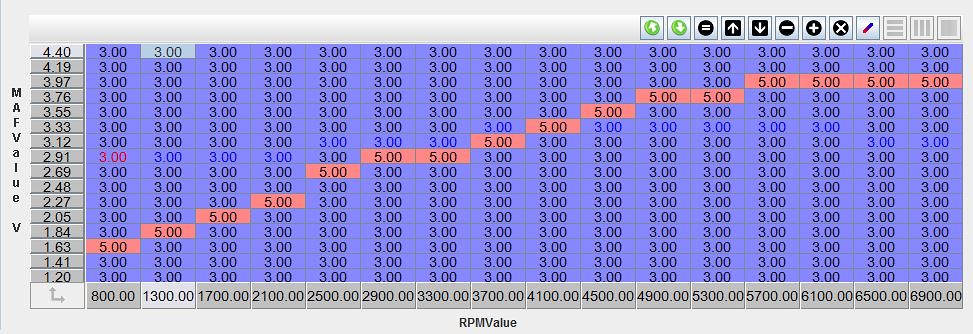
The obvious issue with the current method is the use of the voltage on the main fuel table, the MAF voltage will only increase with total airflow and the engines airflow will only increases with VE and RPM. Thus, as you sweep the engine through its speed range at full throttle you will trace a line across the main fuel table as below, with all the cells below the red line being viable tuning cells and everything above the red line being inaccessible as that amount of airflow is impossible at those engine speeds (actual MAF volts for a BMW M20).
Please ignore the use of "5" in the cells, it was just a number picked to turn the cells red and draw a visual curve.
The simplest solution is to turn the raw MAF volts signal into a load signal.
Having spent a lot of time messing with Motronic systems it feels to me the best way around it is the Pulse width approach using the MAF signal to generate a theoretical ideal stoichiometric pulse width.
From the point of view of RusEFI it has 3 main advantages 1-its computationally efficient, 2-its pretty simple to tune once you get your head around how it works and 3-its out of patent meaning no issues if we use a similar method. (
https://patents.google.com/patent/DE4336813A1/en - expired 2013 due to the 20 year term) I will note this is actually a slight variation on the Bosch method as Bosch calculate for 2 pulses per cycle instead of 1 pulse due to hardware limitations.
It is going to mean that someone wanting to use the MAF/Load system is going to need a little more info on their engine or be able to make reasonable estimates in order to generate the necessary fuel injection constant before they can set the fuel table up but it is not so complex or sensitive that a good estimate of the correct values cannot be found and adjusted later.
With a bit of effort I expect TunerStudio could generate the constant and base table from the inputs.
The basics of the Pulse width calculation is Q/(n*K)=Pulse width where:
Q= Air in KG/Hour
n= RPM
K= Injection constant
Q is easy to find from the MAF transfer function as it is designed to convert the raw voltage into the KG/Hour air flow. It is often possible to get the function from the stock ECU or from data sheets available from the manufacturer. In the case of Bosch stock ECUs this is pretty simple.
n is obviously RPM so that's easy.
K is a calculated injection constant for the injectors used on the engine, which is a little more problematic to work out.
To get K:
1. Max load at peak power RPM
120000/peakpowerRPM= max load possible at peak VE RPM
2. injector flow in kg/h
Injector size in CC*0.0438*number of injectors=Max flow in kg/h
3. Air consumption
PeakpowerRPM/2 * capacity * VE *0.0735 = air consumption in kg/h
4. Fuel consumption
Air kg/h/1.47 = Fuel kg/h
5.Duty cycle at peakVE
Fuel kg/h / Max flow kg/h = Duty cycle [could warn if over .90 or under .60, .80 is ideal as it allows up to 15% enrichment for accell]
6.Injection constant
air kg/h / (PeakRPM*(Max load*duty cycle) = K
The above gives us a max value for the fuel table, a peak fuel flow and K.
Doing this with real values gives the following:
1. Max load value for tables
120000/5000= 21.8ms Max pulse width @100% duty
2. injector flow in kg/h
166cc*0.0438*6 injectors = 43.62Kg/H Max flow
3. Air consumption
5000/2 * 2.49L * 0.98 *0.0735 = 493.22Kg/H air consumption
4. Fuel consumption
493.22/1.47 = 33.55Kg/H Fuel
5.Duty cycle at peakVE
33.55 / 43.66 = 0.769 Duty cycle [could warn if over .90 or under .60, .80 is ideal as it allows up to 15% enrichment for accell]
6.Injection constant
493.22 / (5000*(21.8*0.769) = 0.005349 = K
Which means in ideal circumstances the pulse width at 5000 RPM and 98% VE is:
493.22 /(5000*0.005349) = 16.76ms pulse, which is actually pretty damn close to the required pulse with for stoichiometric fueling.
Before going much further it's wise to discuss the Y axis of the fuel table, to get an estimate of the max needed load value it works ok to perform calculation 1 for the peak engine operating speed, in the case above it comes out at 17.142ms and is essentially a pulse width we cannot physically exceed at 7000 RPM. If we tried to pulse the injectors for this long at peak RPM they would be at 100% duty cycle so we kind of need to size our injectors with this in mind.
Thus our Y axis is 17-1/16 = 1ms per row (pretty convenient for this case)
Using what we did above we can populate the main fuel table as below.
Where the X axis is the RPM as normal, the Y axis is working off our calculated stoichiometric load and the values in the table are the actual output stoichiometric pulse width.
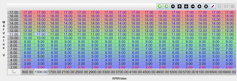
To tune the part load fueling it is simply a case of adjusting the pulse widths up and down to suit the real needs of the engine. The calculated pulse width is going to be close but does not account of the gas dynamics inside the intact tract or any forced enrichment or leaning that the tuner desires.
For the ECU to calculate the final pulse width is pretty computationally efficient:
1. Read analog chanel for MAF
2. Lookup table for volts to air kg/h
3. If no MAF value get value from TPS table
4. Air kg/h / (rpm*K)
5. Add warmup correction value [best as a simple multiplier]
6. Add value from Barometric table [best as a simple multiplier]
7. Read stoich pulse width from Fuel table
8. Add value from acceleration table [best as a simple multiplier]
9. Output final fuel pulse width
If we are going to make this work with a fail safe mode we need a TPS to air flow table, I can figure that one out.
Possible figure out some barometric correction factors but a table that is flat mapped to no correction works for initial tuning.
At the moment best I can figure out is the following pro/cons which I'm happy to revise if anyone can think of anything else.
Advantages -
1. Allows more of fuel table to be used at lower RPM/airflow which means better fueling at part loads and low air flows.
2. Is essentially a VE/speed density system based on the MAF sensor
3. Relatively resistant to changes in engine condition and architecture as the air flow will increase or decrease with corresponding pulse width changes.
4. Can fail safe by generating load value from TPS provide we have a TPS to air flow table. (which can be calculated from geometry)
5. MAF type can be changed quick and easy only tuning one table
6. More robust OEM style strategy that's proven itself on many cars
7. Will improve part throttle emissions so should help those of use that have to do part load emissions checks.
8. Barometric correction can be applied to do a boosted MAF setup or account for altitude if the correction factors were in place.
9. Much better transient fueling possible due to 1.
10. Acceleration enrichment can be simplified to Load Vs TPS (need to flesh this out in my head a bit more before I comment further).
11. Very simple base map using calculated pulse widths, the calculated pulse widths should always come up pretty close to the actual width needed for stoichiometric operation meaning the base table can simply be the Y axis value all the way across the row.
12. Possible to warn about undersize or oversize injectors via the tuner studio K factor calculations. If your calculated stoich pulse widths give duty cycles that are too high then it is immediately obvious that your injectors are too small to deliver the extra enrichment.
13. Warmup enrichment easily applied to all running conditions as it only needs to be a correction factor that the pulse width is multiplied by.
14. Allows ECU to estimate AFR based on load pulse width vs final pulse width and then compare this to AFR read from the WB02
15. Relatively insensitive to air temperatures as MAF will responds to the increased density of the air and greater temp difference with the hot sensing element, IAT only really needed for TPS limp mode or fine correction.
Disadvantages -
1. Harder to program - needs more code to perform the same function as the pure Volts method.
2. Harder to understand calculation method in the first instance
3. Requires known MAF curve/transfer function to create the MAF table
4. Requires more inputs to Tunerstudio and more math in Tunerstudio to generate the main fuel table
5. Would require a TPS to load table for fail safe
6. Might not play nice with MAF auto tune methods
7. Method not really suitable for large amounts of boost or pure racing engine builds due to difficulty of getting peak pulse widths correct [but they should be SD or AN anyway right?]
One final thing to note is that with this method I would be using about 90% of the main fuel table across the range as shown below:
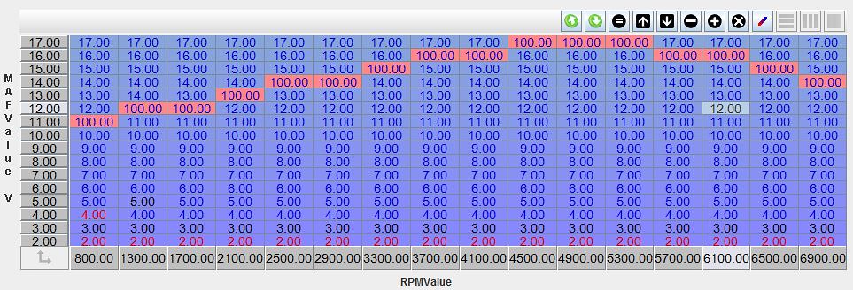
The 100 values I have put in there indicate the highest cell that would be accessed so everything below that line is fair game for tuning meaning much better adjustments of fueling at lower loads and RPMs.
* A few notes on this Vs motronic classics method
The older Motronic units use a slight variation of this method as shown in the patent I posted, the hardware limitations of the ECU limit all fueling equations to 12.75ms load max (255 or 0xFF in hex) as it cannot count any higher, thus the load is calculated as though the pulse width was 1/2 the sequential width with the injectors reverting to batch fire above a certain load and speed.
The relative slowness of the processor and poor FPU mean that all the values are scaled in some way to make them whole numbers, K for instance is actually 1/400*K which results in a number in the 10 thousands instead of a really small decimal.
RPM is factored by 40 meaning that 7000rpm=175 or 0xAF with the max value being 0xFF or 10200 RPM
The main fuel table is actually a correction factor table, with 128 being no correction 0 being -100% and 255 being +100%. This is also true of a lot of other fuel tables.
Basically everything is tweaked and factored to maker life as easy as possible for the ECU processor making the actual Motronic method much harder to tune, harder to reverse engineer and a much dirtier implementation.
With better hardware we can take the principal behind the old method and actually apply it in a cleaner simpler and more easily tuned fashion.