Page 1 of 1
CAD file for Festiva ECU PCB
Posted: Mon Apr 28, 2014 9:20 pm
by Rocketman
Here's the CAD file I worked up for the PCB in the stock Ford Festiva B3 ECU housing.
http://werbatfik.com/uplimg/cad/B3_ECU_PCB.dwg

I can convert to dxf format as needed. I did not test-cut it on my CNC yet to check fitment. But I'm fairly confident it will work. The hashed are is the general location of the connector, use any one of the the three bolt hole to locate it on the board - there's a fair amount of tolerance there.
Re: CAD file for Festiva ECU PCB
Posted: Mon Apr 28, 2014 9:26 pm
by AndreyB
Cool! That's for the 64p connector, right? Looks like the full 64p connector, not the smaller version without the middle 22p.
How do we convince you to cut & test fit it?

Next step would be getting this into KiCad. Jared, do you know a way to bring this into KiCad?
Re: CAD file for Festiva ECU PCB
Posted: Mon Apr 28, 2014 11:39 pm
by kb1gtt
I tried this once in the past, but wasn't very happy with the results. I have tried this TTCONV program noted here
http://wiki.xtronics.com/index.php/Pcbnew#Importing_DXF_-_DWG as well I seem to have found a program or web page that would convert a DWG to a gerber file. The the gerber file could be imported into kicad. I seem to recall I ended up drawing the stuff by hand when all was said and done. Last I was playing with it was when I was playing with the Cinch enclosure stuff. I'll add it to my list to see if I can make it play nice.
Re: CAD file for Festiva ECU PCB
Posted: Tue Apr 29, 2014 12:22 am
by kb1gtt
I'm remembering the issues with getting the TTConv dependencies sorted out. I seem to recall I got it working once upon a time, but I'm hitting some bumps in the road now.
About the above graphic, a print 1:1 on some paper or cardboard and a pair of scissors can go a long way with very little programming or effort.
Re: CAD file for Festiva ECU PCB
Posted: Tue Apr 29, 2014 2:27 am
by kb1gtt
I got it working, or at least ttconv opens now. I followed the instructions found here
http://permalink.gmane.org/gmane.comp.cad.kicad.user/5677 it worked for windows 32 bit on win7. I seem to recall from my prior experience that it did not play nice with 64 bit, had to be 32 bit. Any how it opens, but wants to convert DXF not DWG. Can I get a copy of the file in DXF. Also note I get this message when I open the program. For others that might try this, draftsight is free as in beer, with registration, and works with DWG and DXF very well.
Re: CAD file for Festiva ECU PCB
Posted: Wed Apr 30, 2014 10:57 pm
by kb1gtt
I finally got Draftsight installed. Then I saved as dxf, then ttconv to make into a module. Here is the module.
Re: CAD file for Festiva ECU PCB
Posted: Wed Apr 30, 2014 11:00 pm
by AndreyB
Re: CAD file for Festiva ECU PCB
Posted: Thu May 01, 2014 11:42 pm
by AndreyB
kb1gtt wrote:a print 1:1 on some paper
Let's make some tiny changes to make this even better.
Let's make it universal so that we can use it both with 48 pin and 64 pin connectors, maybe even focus on 64 pin connector because it's easier to acquire.
I believe you have have 079721-2351
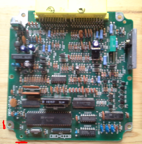
and 079721-3350
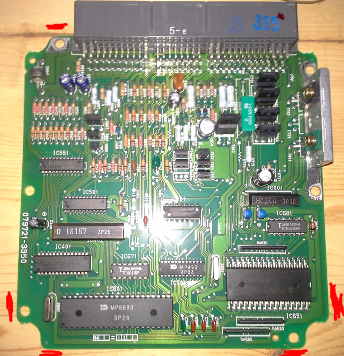
has couple of mounting holes at different spots.
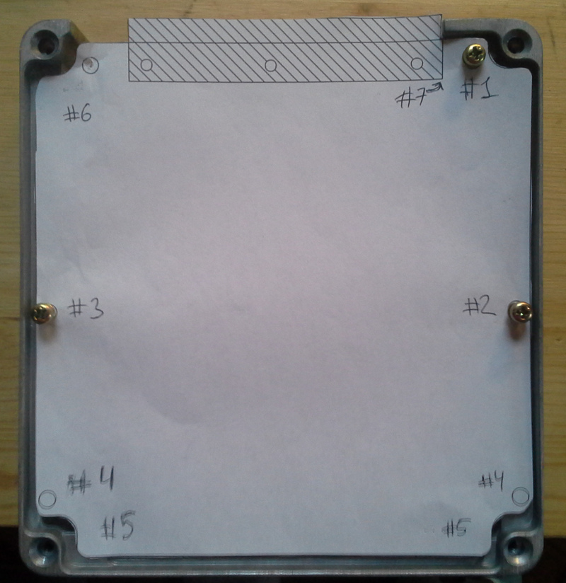
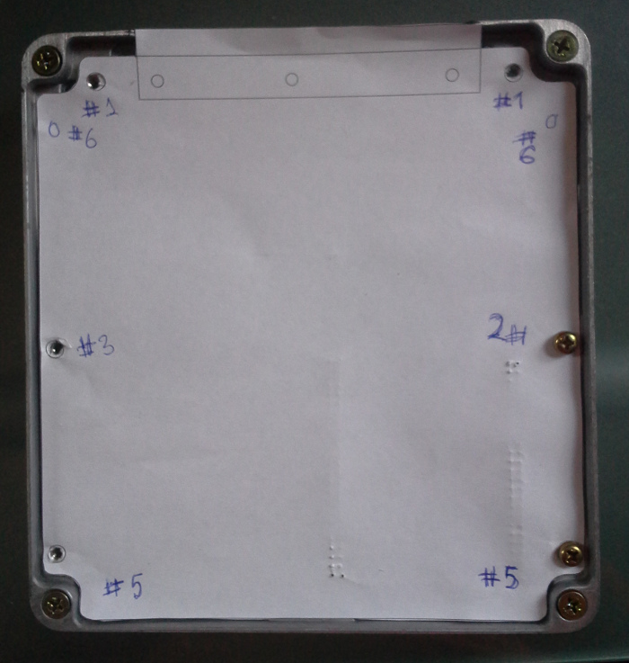
So #1, #2 and #3 are perfect, let's use them as reference points.
#4 - we need to lower these holes a little bit, looks like 59mm between #2/#3 and #4.
#5 - let's widen this lower section by couple mm on each side and expand the board 2mm down, that's so that we can add the missing lower mounting hole (see the 3350 board - looks like that lower-right hole is in the same spot as the unused lower-left hole on the 2351 board, just mirrored. We can probably add these lower holes on both sides just in case.
#6 - these top holes are 64.5mm above the #2/#3 holes.
#7 - we need to move the right edge of the connector 2mm to the left, the way it is there is not much clearance. There is a drawing of that connector @
http://www.te.com/catalog/pn/en/176122-6 - can you take the connector width & mounting holes locations from there?
I hope these changes make sense.
Re: CAD file for Festiva ECU PCB
Posted: Fri May 02, 2014 12:27 am
by puff
shall i create a cad file for some russian ecu board?
Re: CAD file for Festiva ECU PCB
Posted: Fri May 02, 2014 1:24 am
by AndreyB
Puff, only if you have stock header available
Re: CAD file for Festiva ECU PCB
Posted: Sat May 03, 2014 6:43 pm
by kb1gtt
I started to play with merging frank and this outline. See attached.
Re: CAD file for Festiva ECU PCB
Posted: Sat May 03, 2014 11:09 pm
by AndreyB
While Festiva has a 48 pin connector, it's easier to buy a 64 pin connector version - with a 3rd plug in the middle.
On this picture, the box on the left is 1993 Mazda Protege 1.8 LX Auto. I believe at least some SOHC auto are 64 pin also.
On the right we see a taller compatible box - that's Mazda 626 with a v6. These are taller because they have two PCB inside connected via a ribbon cable, does not matter for us - the primary PCB is from the same 079721 family.
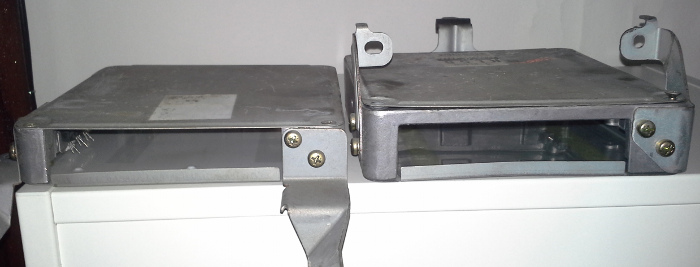
In my greedy junk yard these were $11 each.
Re: CAD file for Festiva ECU PCB
Posted: Sat May 03, 2014 11:27 pm
by AndreyB
On this picture, note how 55-60% of the plastic part is sticking outside of the PCB outline. Also the heat sink is visible:

Re: CAD file for Festiva ECU PCB
Posted: Sun May 04, 2014 9:27 pm
by kb1gtt
For documentation purposes, the TTConv0.2 "Scale Unit DXF>Kicad" was 394
Re: CAD file for Festiva ECU PCB
Posted: Mon May 19, 2014 5:34 pm
by AndreyB
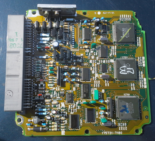
Surprise-surprise, 1994 4 cyl Toyota Camry uses the same ECU box, their PCB code is 175731-7180
Re: CAD file for Festiva ECU PCB
Posted: Tue May 20, 2014 4:19 am
by Rocketman
The only other ECU's I have here are the 52 pin which is also quite common between Mazda/Toyota & others.
Re: CAD file for Festiva ECU PCB
Posted: Sat May 31, 2014 12:27 am
by AndreyB
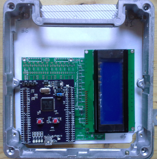
New draft placement
Key ideas: we will have both the pads for stm32f407VG right on the PCB, and 100 holes for discovery. This case one would be able to either mount everything to the PCB (hardcore soldering), or solder discovery to the board, or solder connectors for discovery (risk of discovery falling out)
The screen would be mounted on stand-offs, so it would not be wasting space on the PCB.
Re: CAD file for Festiva ECU PCB
Posted: Thu Jun 05, 2014 1:20 am
by AndreyB
@ has improved the outline a bit:
Re: CAD file for Festiva ECU PCB
Posted: Thu Jun 05, 2014 2:43 am
by kb1gtt
Great.
Is there a copy I can grab to convert to KICAD? Or perhaps someone else has already grabbed it and converted to KICAD. I keep hoping I'll get to take a stab at Frankenso, but I keep having to bump hobby stuff to a lower priority

Re: CAD file for Festiva ECU PCB
Posted: Thu Jun 05, 2014 3:12 am
by AndreyB
this 2nd version was made from your .brd file - I've converted it to .kicad_pcb
https://svn.code.sf.net/p/rusefi/code/trunk/hardware/rusefi_lib/outlines/
I am hoping to place the discovery outline at the right spot of the denso PCB outline tomorrow - I have the location on my paper prototype, need to take measurements.