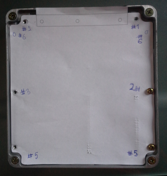
kb1gtt wrote:a print 1:1 on some paper
Let's make some tiny changes to make this even better.
Let's make it universal so that we can use it both with 48 pin and 64 pin connectors, maybe even focus on 64 pin connector because it's easier to acquire.
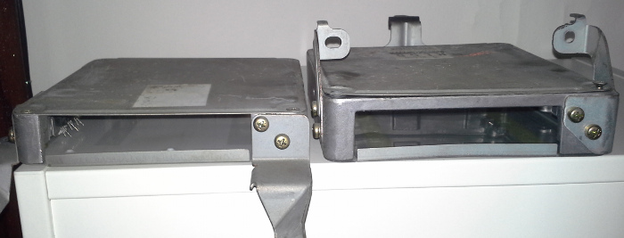
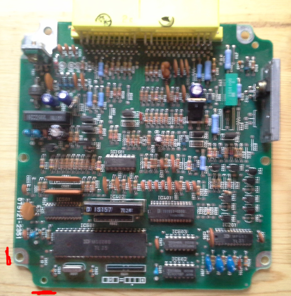
I believe you have have 079721-2351
and 079721-3350
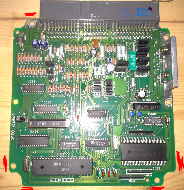
has couple of mounting holes at different spots.
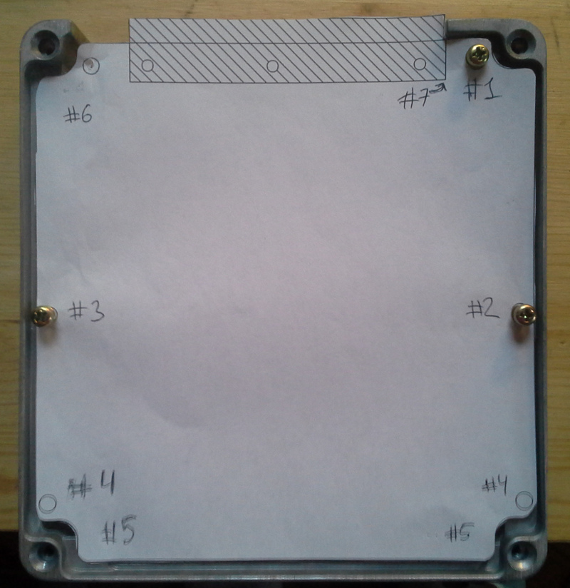
So #1, #2 and #3 are perfect, let's use them as reference points.
#4 - we need to lower these holes a little bit, looks like 59mm between #2/#3 and #4.
#5 - let's widen this lower section by couple mm on each side and expand the board 2mm down, that's so that we can add the missing lower mounting hole (see the 3350 board - looks like that lower-right hole is in the same spot as the unused lower-left hole on the 2351 board, just mirrored. We can probably add these lower holes on both sides just in case.
#6 - these top holes are 64.5mm above the #2/#3 holes.
#7 - we need to move the right edge of the connector 2mm to the left, the way it is there is not much clearance. There is a drawing of that connector @
http://www.te.com/catalog/pn/en/176122-6 - can you take the connector width & mounting holes locations from there?
I hope these changes make sense.