Does the display have the termination resistor internal to it? Do you measure 120 ohms across terminals J and L? Also do you have a 120 ohm across your end? You will need the 120 ohm at each end of the bus. Your bus is short. If you need to add a 120 to the display, you could probably get by with two paralleled 120's at your end.
kb1gtt wrote:Does the display have the termination resistor internal to it? Do you measure 120 ohms across terminals J and L? Also do you have a 120 ohm across your end?
Just checked - yes the cluster has 120 ohm between the CAN wires, and so does my transmitter end.
I am using stm32 native, behind the scene CAN peripheral. I am pretty sure it's just some stupid bug, I simply need someone to review the code and spot something off.
Will try googling the exact wiring later, there must be info on which CAN wire is which.
can't get it what it means - high impedance, low impedance... but when you look at the transceiver pinout, you'll see that it is powered either from 5V or from 3V, which seemingly implies that this voltage levels could be found on the can bus. How does the transceiver sense the lines?
Have you checked what's going on with logic analyzer?
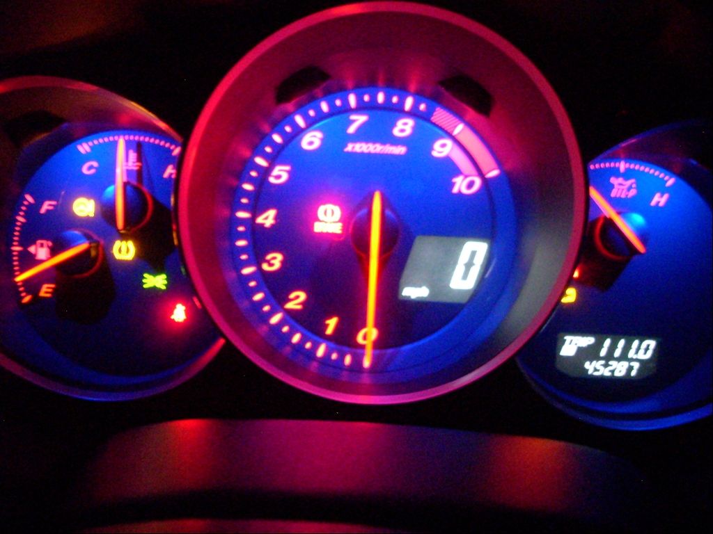
If anyone is interested - I've paid $30 for the cluster with the piece of harness, I was risking - it has mounting taps broken off and was being sold as "for parts"
Normal eBay price seems to be about ~$50 for cluster and ~$20 for the piece of harness
just got it with harness ~ $40
turns on, with lights.
tomorrow gonna try it with rusefi.
mine has the side gauges reversed: oil stuff is to the left, fuel and temp - to the right.
need to know what is the second, bigger connector - what are these wires.
neet more info on fuel gauge.
need to figure out the odo thing.
people say, CLT needle doesn't react to the actual fluctuations in temerature once it reaches the working conditions, which is weird. the same reportedly refers to oil pressure - it's either no pressure, or normal pressure.
what are these three interior light system wire in the smaller connector?
what is d) (brn/blk) wire in the smaller connector?
how do i switch it from mph to kmh?
is there a chance to feed some other switched signals to this cluster over CAN?
e.g. oil pressure switch?
traction control (I'd like to indicate diff lock condition instead)
parking brake?
coolant level?
could it switch on the battery light if the engine is running (rpm>0), and the voltage is lower than 13V?
could it switch on the check engine light via CAN, not a separate contact?
are there any chances to implement trip meter? (though, involves too many CAN messages, and probably requires some really fancy maths)
will it feed speed signal from rusefi?
вся процитированная тобой часть стоит внутри #if - то есть выполняется только если в системе имеется датчик скорости?
то есть без датчика скорости автомобиля на панели приборов даже обороты отображаться не будут?
плюс почему-то 144 и 154 строки дублируют номер пакета, и после формирования первого пакет так и не отправляется...
вот патчик для температуры и миганий лампочками. правда, собирать не пробовал...
а для одометра нужно будет, наверное, переделать тот коэффициент датчика скорости в более удобоваримое значение (сколько импульсов на метр/километр?), и из кода датчика скорости делать колбеки, что ли? причем только в случае, если выбрана приборка мазды? как иначе заставлять его отправлять can сообщение с меняющимся вторым байтом каждые 33 метра пробега?
You do not have the required permissions to view the files attached to this post.
puff wrote:can't get it what it means - high impedance, low impedance... but when you look at the transceiver pinout, you'll see that it is powered either from 5V or from 3V, which seemingly implies that this voltage levels could be found on the can bus. How does the transceiver sense the lines?
Have you checked what's going on with logic analyzer?
CANbus is differential but the signal level is only around 2V so it doesn't matter if its 3v3 or 5v supply. The common mode voltage does matter though so you need a good common ground.