Great feed back, and thanks. Don't worry so much about the feeling of being critical, I generally look for content before emotion. What doesn't kill it will only make it stronger.
As a quick note on the history of Frankenso and Frankenstein boards. We originally developed several small boards which we eventually smashed together to make the Frankenstein board. AKA it was our baby made from various bits and pieces, as well it often plays nice with replacing sections. Then Frankenso was the same thing as Frankenstein but for a Denso based system. This power supply is one of the sub circuits used on these other Frank series boards.
I was not aware of ISO16750-2. I just added it to the wiki.
http://rusefi.com/wiki/index.php?title=Manual:Hardware
I have found a PDF copy of the 2006 spec here
http://static.ednchina.com/mcu/2009/11/6/2f9e7f31-3753-49a5-b3cc-e9b25fb072a3.pdf which has been attached. Hmmm, that seems to have an IHS copyright note on it, so this link may need to go away. This copy from 2003 doesn't have that copyright note.
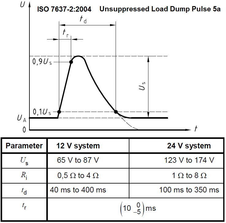
http://i01.yizimg.com/upload/175936/200793211156599229307.pdf I didn't find the 100v-ish pulse specs in this standard. There are similar specs in 7637-2. Last I recall 7637-2 specified the surge pulse, but didn't specify how often, or for how long it had to sustain. However I'm also working off random bits found on the interwebs, so I might not have the full spec.
Also I found this
http://www.vishay.com/docs/49748/49748.pdf which has lots of great scope traces and information that I find interesting.
I agree the TVS diodes are undersized, and should be changed for larger ones. They are thru hole components and larger ones should be easy to install, I just haven't gotten around to finding the ones should be used. I haven't figured out which ones as I didn't have a good spec for what kinds of surging I should expect. As well there should be an upstream RF snubber which effects how much energy these clamping diodes would see. What's in there now was based on easy to obtain low cost china parts which would likely "work" for a large single surge, but would not survive sustained surges happening every ?? seconds. I don't have proper facilities to test it, so it has been a step in the right direction, but is probably a weak design. It's better than nothing, but it also really isn't 100% correct.
Do you have a suggested schematic or parts list for the audio amplifier circuit? It would be handy if I had some kind of test fixture to do better testing. There are several ripple rejection signals I would like to test.
I also agree it should have some RF choking that helps keep the fast transients off the PCB. I was hoping to use a thru hole resistor, as a fuse / RF choke, but have done a bunch of testing and found that this is not likely to work. With my DSOquad, I did a sweep of several different wire wound resistors and found that under 100kHz they just don't have the RF blocking inductance required to choke off the RF. The program for the DSOquad is linked here
http://essentialscrap.com/dsoquad/freq.html I've been looking at replacing F1 with something like this
https://octopart.com/elc-18b470l-panasonic-392391 I'd like to find an inductor that will burn up before some down stream short burns up a PCB trace or something like that.
About the on-board fuse. We expect that there will be an upstream fuse that's smaller and will blow before this fuse blows. I agree that under these surge conditions it should not blow the fuse. However the design now would blow the fuse under several 12V surge conditions. This is better than blowing the MCU or burning a trace on the PCB, but it's also not as good as I would like it to be. We also don't have the quality control systems in place like an OEM. This fuse is partly designed to protect the board when someone doesn't provide proper fusing up steam. Basically if the board was going to go up in flames any how, it would be nice if those flames happened in a place that was easily replaced. Keep in mind that we do not have control over random peoples install practices, while an OEM can ensure that things like a proper up stream fuse has been installed.
Take note there is this file for frankenso
https://sourceforge.net/p/rusefi/code/HEAD/tree/trunk/hardware/frankenso/known_issues.txt which list pretty much every item that someone has commented to me. There are some things that haven't been addressed, and many that have been addressed. If you see something you think should be addressed feel free to post a suggested addition to that list. I work on this stuff in 10 minute windows of time, I use that list to remind me what to look at when I get those short windows where I can work on it. Right now the RF choke and fuse blowing issue are triggered by this entry.
Code: Select all
69) Change F1 to a wire wound resistor which will also be the weak link and act like a fuse before the PCB breaks, while also snubbing RF
Well that's my 10 minutes for this morning. Welcome along and feel free to comment and make suggestions.
You do not have the required permissions to view the files attached to this post.


