Hi from northern Germany
Posted: Fri Aug 07, 2015 9:13 pm
hi, i'm Klas from Hamburg, Germany.
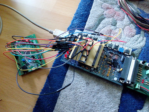
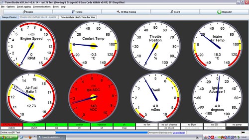
after i got my stm32 development board and a bit reading it seams i got it working on the bench. at least everything works using the java console as far as i can tell.
next step will be to adapt it to my ecu board that was made for a MC68HC908 and if that works out ok, a new pcb layout may be in order.
so i have to start asking stupid questions.
my first test engine uses a throttle body injection with a single low impedance injector, does rusefi support PWM control of the injector? or will i have to use a resistor for current control?
it uses a dizzy but timing and dwell is ecu controled. that shouldn't be a problem, should it?
idle control is via stepper. i found stepper is supported and bought a A4988 board. thats right i guess.
being a british engine it uses it's own trigger pattern at the flywheel. would be great if that could be supported directly. one it a 36-1-1, with the missing teeth 180° apart, both at TDC. the other, later is more complicated, 36-1-1-1-1, the gaps are at 30°, 60°, 210°and 250° IIRC. called Rover #1 and Rover#2 at other ecu systems.
for beginning i have a 36-1 fitted to the pulley, back from the days i used a EDIS based ignition control. so i hope to have it up and running quite easily.
but my most important question is, is there a recommended pin usage? i found some tables, but they don't seem to be identical. as a guess because they are for differend pcbs. but i'm not sure.